User Manual Router with 802.
FCC Compliance NOTE: This equipment has been tested and found to comply with the limits for a Class B digital device, pursuant to Part 15 of the FCC Rules. These limits are designed to provide reasonable protection against harmful interference in a residential installation. This equipment generates, uses and can radiate radio frequency energy and, if not installed and used in accordance with the instructions, may cause harmful interference to radio communications.
Contents INTRODUCTION............................................................................................................. 1 THE PRODUCT .................................................................................................................. 1 PRODUCT FEATURES ........................................................................................................ 1 BASIC IP NETWORKING ...................................................................................................
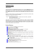
INTRODUCTION The Product The product is based on the IEEE 802.11g standard, which is the latest 54Mbps Wireless LAN (WLAN) standard. This standard is five times faster than the widely deployed WiFi (802.11b) products that are found in homes, airport and public wireless hotspots. Because 802.11g uses the same 2.4GHz frequency band, the product is fully interoperable with existing WiFi cards and devices.
Basic IP Networking IP = Internet Protocol IP stands for Internet Protocol. In an IP network, every device has a unique IP Address (For example: 192.168.1.35) to identify itself. There are two ways of assigning an IP address to a PC or Router: Static and Automatic (DHCP). Static IP addresses are keyed-in manually, while Dynamic IPs are distributed by a DHCP Server.
Wireless LAN A Wireless LAN (WLAN) is a computer network that transmits and receives data with radio signals instead of using cables. WLANs have become common in homes, offices, airports and public Hotspots. WLAN can support the same applications and software that run on a wired network (LAN). Besides supporting the same software and functions, WLAN brings greater convenience and eliminates the need to lay Ethernet cables in a home or office. The Router is based on the finalised 802.11g standard.
Make sure that the WLAN signals do not have to pass through too many concrete walls and metal structures to reach the client. Make sure that APs are located far away from one another to avoid interference. Interference Interference happens when 2 APs with the same channels are placed near to one another. The speed of the network drops and the signal strength fluctuates wildly. Roaming Association happens when the SSID, Encryption and MAC Address Control settings are correct between the AP and client.
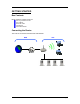
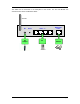
GETTING STARTED Box Contents Kindly check the contents of the box: 802.11g Wireless Router DC Adapter Ethernet cable CD Manual Quick Start Guide Connecting the Router The router is connected to the WAN and LAN networks.
The cables are all connected to the back-panel of the Router. The PCs and Modem are connected to the Router via Ethernet cables.
Quick Start Configuration (For DSL Modems) This section is a quick-start guide applicable to most users. This assumes that the user is connecting the WAN port to a ADSL modem. 1. Connect the network as shown previously. Switch on the Modem BEFORE you switch on the Router. Every time. Check that the WAN light on the Router lights up. If your PC is connected via Ethernet cable, check that the corresponding LAN LED lights up on the Router.
WEB CONFIGURATION In every Router Web Configuration page, the left panel is the navigation menu containing the main sections. The right-side frame is where the detailed configuration is done. Configuration panel Navigation panel Remember that after every configuration change, it is necessary to: - Click Apply on the page. Reboot the Router. The changes take effect only AFTER Reboot.
Quick Configuration This page contains the most important settings to get the Router functioning in either a home/ small office environment. Basically, this page specifies what the WAN port is connected to. DHCP Client: By default, or when you boot up the Router for the first time, the WAN port is in DHCP Client mode. The WAN port will obtain an IP Address from an upstream DHCP Server or Cable modem. ADSL Modem / PPPoE: Select this option if the WAN is connected to an ADSL Modem.
Status System Log This page shows the system log of the Router. You can Enable/Disable the logging. Station MAC Address of your Router. MAC Address of a active CardBus. The Station page shows the status and MAC Addresses of the WLAN network.
Statistics Signal-to-Noise Ratio. Ethernet and Wireless Statistics show the statistics of the traffic handled by the Router. The Signal Strength parameter shows the Signal-to-Noise ratio of the Wireless link. The higher the number, the better the link.
LAN & DHCP Configuration This page is for the configuration of the Router’s internal (LAN) IP Address and the properties of the built-in DHCP Server. Take note that the built-in DHCP Server distributes IP Addresses to both the LAN ports and the WLAN clients. LAN Setting LAN IP address: This is where you assign a local IP address to your router’s LAN port. The factory default value is 10.0.0.1. It is not recommended to change the LAN address for no reason.
(Note: This setting will only take effect when User defined is selected under DHCP address pool selection.) Lease Time: The amount of time a network computer will be allowed to connect with the DHCP Server. By default, the lease time is 1 week. (Note: This setting will only take effect when User defined is selected under DHCP address pool selection.
WAN Configuration This page allows you to configure how the WAN is connected. For ADSL modem users, you have to use PPP. If you connect the WAN to an existing Ethernet network, you have to set either Static WAN or DHCP Client. The new Router is in DHCP Client mode. Quick Configuration page would actually take care of your WAN settings. This WAN Configuration page is for advanced users to fine-tune their network. PPP Configuration This section lets you configure the PPP dial-up settings.
Static WAN Configuration This section lets you configure Static WAN IP settings. WAN Static IP: Enter the static IP address. WAN Subnet Mask: Enter the subnet mask. WAN Gateway: Enter the WAN Gateway IP. DNS: Enter the DNS Server IP Address. When in DHCP client mode, these 4 columns show the IP settings obtained from the network. DHCP Client This section lets you configure the WAN port as a DHCP Client. This is the Factory Default mode. Enable DHCP Client?: Select to enable WAN as a DHCP Client.
Bridge The Router can also be used as a Wireless Bridge. This is used when it is not advisable to lay an Ethernet line over a distance. Two routers can be set up to connect over this distance, acting as the wired backbone. LAN LAN Ethernet Cable Switch Switch Equivalent to: Wireless Bridge LAN LAN Router Router To establish the Bridge link, 1. Connect your PC to Router1’s LAN port. Do not connect anything to the WAN. 2. Get Router2’s MAC Address from Router2’s Station Information. 1.
4. 5. 6. 7. 8. 9. Change Router1’s LAN IP and subnet so that it can exist in LAN1. Make sure that LAN1 and LAN2 are also in the same subnet! Disable Router1’s DHCP Server. Apply and Reboot. Connect the LAN port of Router1 to LAN1. Repeat the process for Router2. MAC Address Router Router MAC Address 10. Ensure that the SSID and Channel are the same for both Routers.
Wireless This page lets you configure the Wireless settings. There are 3 sections: Radio, Security, Advanced. Radio Settings SSID: Service Set Identifier. It is a sequence of characters that uniquely names a Wireless LAN. This name allows PCs to connect to the correct Wireless Access Point when multiple Access Points (or Wireless Routers) operate in the same location. Channel: The radio channel number. Hide SSID: When this is ticked, the router will not broadcast the SSID.
To enable MAC Address Filtering, click on the link MAC Address Filter Table. Only valid computers (whose MAC addresses are in the MAC address table) would be allowed to access the router. Enable MAC Access Control: Tick the box to enable MAC Address Filtering. MAC Address Add/Delete: Enter the MAC Address in the format 00:11:22:33:44:55 to be Added or Deleted from the table. Allowed MAC Addresses: Displays the MAC Addresses currently allowed.
Security This section allows you to configure wireless encryption to prevent unwelcome parties from reading your traffic. Authentication can also be configured to block outsiders from accessing your network. Security Mode. Enable Encryption: Tick the box to enable the following suite of Encryption and Authentication features. Open-System: When chosen, the Key is not used for authentication. It is only used for encryption. Open-System uses Static Keys for encryption.
Shared Key 1-4: For Open-System and Shared-Key, the Key is to be entered in the boxes. The SAME Key must be entered in both the Router and Client. Take note that there is a different Key length for a different number of encryption bits. 152 bits is the most secure, but make sure that your Client card supports it. The last point to take note is that if you use Key 4 on the Router, you must also use Key 4 on the Client, for example. The same logic applies for Keys 1-3.
NAT This page lets you configure your NAT (Network Address Translation). Enable NAT?: Tick to enable NAT. NAT allows the sharing of one broadband connection between multiple PCs. This setting is for advanced users only. For almost all purposes, ENABLE the NAT.
DMZ Configuration The DMZ (De-Militarized Zone) Configuration page lets you map a local computer to this zone. By default, the Router protects the PCs from the Internet. The local PCs can access the Internet (WAN) but not vice versa. Local PCs are hidden behind the NAT and Firewall. DMZ is used when you want to expose that PC to the Internet. For example, you want to set up a Web Server or Game Server such that outsiders can access from the Internet. Enable DMZ?: Tick to enable DMZ.
SNTP Configuration This page allows you to configure the Router to automatically synchronize its time. SNTP (Simple Network Time Protocol) is a standard that allows devices to synchronize their time according to SNTP Servers on the Internet. Enable SNTP: Click to enable the SNTP feature. SNTP Server IP Address: Enter the IP Address of the SNTP Server on the Internet that you want to use for synchronization. Time Zone: Enter your local time zone.
Port Forwarding This page allows you to configure Port Forwarding. This feature is used when you need to set up Servers in the LAN. Traffic initiated from the WAN (Internet) is normally blocked. Port forwarding allows the specific type of traffic to pass through the Router to reach the Server in the LAN. Examples of these Servers are Web Servers and Game Servers. Add new rule: This is where you specify the port to be map on the local computer.
Common application port values: Application Port values Type FTP 21 TCP Web Server 80 TCP Telnet 23 TCP While all the ports of the PC in the DMZ are exposed to the Internet, Port Forwarding only allows the ports that you specified to be opened up. DMZ can be understood as a form of Port Forwarding where ALL the ports are forwarded. DMZ is usually easier to set up, but Port Forwarding is more secure.
Filter This page is for the configuration of filters to block unwanted traffic from WAN (Internet). Enable filtering: Tick to enable the filtering features on this page. Blocked Services: Tick beside the Service to block this Service from the Router. FTP: Tick to disable FTP services (for firmware upgrade) from the Internet. Telnet: Tick to disable telnet (a form of configuration tool) from the Internet. HTTP: Tick to disable Web configuration by users in the Internet.
Enable: Tick to enable Packet Filtering by volume. These 2 settings are used to protect the limited WLAN bandwidth. Broadcast Threshold: Enter the number of Broadcast packets (in Packets/second) to be allowed to travel between WAN and WLAN. Typical values can be 100. Multicast Threshold: Enter the number of Multicast packets (in Packets/second) to be allowed to travel between WAN and WLAN. Typical values can be 100.
Web Security Configuration This page allows you to configure Administrator’s security for the Router. Enable Web Security: Tick the box and the Router would challenge every access to its Configuration Webpage. This feature prevents unauthorized configuration of your Router. By default, you are not challenged when you try to access the Configuration pages.
Admin Username and Password These 2 pages allow you to change the Administrator’s Username and Password. Every attempt to access the configuration pages of the router would be challenged, and the Administrator’s Username and Password have to be used. The default username is admin. The default password is also admin. After every Factory Reset, the Router reverts to this combination.
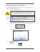
Firmware Update This page allows you to update the firmware (software) of the Router. New firmwares are issued to improve the performance and add features to the product. The Router is the FTP (File Transfer Protocol) client and your PC has to run a FTP Server using a simple utility software. Step 1. Unzip Firmware Files 1. Create a directory in your C Drive hard disk and name it firmware. 2. Unzip the firmware files and save them into your new directory c:\firmware\ Step 2. Set up FTP Server 1.
3. We have to Create a new user that has the name and password “admin”. 4. Enter the User Name as admin. 5. Enter the password twice as admin. 6. 7. Type in c:\firmware as the Home Directory. Click Done. The FTP Server is now set up on your PC. You can proceed to Step 3. The account has already been set up. In future, you would only need to do Step 1 and 2 and select the account admin, instead of default or anonymous.
Step 3. Update Firmware 1. 2. Leave the original settings on the page intact. They have been pre-configured for you. If you have accidentally changed the settings, configure using the picture below. The FTP Password is admin. Current firmware version. 3. Click. 2. Enter here. 1. Read here. 4. Click. 3. 4. 5. Enter your PC’s IP Address. To help you, the Router suggests it to you on the web page. Save the settings. Click Update and wait at least 40 seconds rebooting the Router.
Save Configuration This page allows you to save a “Good” Configuration into the Router’s memory. After you have successfully configured the Router, you can save this “Good Config” into memory. You can retrieve this “Good Config” later, if you have messed up some settings and do not know what was the previous working setting. If you have even forgotten the password to get into the configuration pages, you would have to do a Factory Reset to the Router.
PC CONFIGURATION The Router’s function is to connect multiple PCs to the Internet. In addition to configuring the Router, the PCs’ IP settings would also need to be configured. It is easiest to use DHCP client for the PCs. This is also the default whenever you: a. Install a new Wireless PCMCIA/Cardbus card, or b. When you plug a Ethernet cable into your PC for the first time. Fortunately, in default mode, the Router’s DHCP Server is on.
5. In the box, click on Internet Protocol (TCP/IP). Make sure there is a tick in the box for TCP/IP. 6. Use automatic for both the settings. Click OK and close all windows. 7. Windows 98SE and ME may prompt you for a reboot. DHCP Client has been set up on your PC. Make sure you do a Factory Reset to the Router and configure your broadband account again.
FACTORY RESET When you have wrongly configured the Router and wish to start all over again, you can perform a Factory Reset to restore the Router to its original state. Simply use a paper clip or any pointed object to press in the hole for 5-10 seconds and release.