
Instructions / Assembly

Electrical Connection
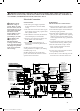
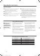
POWER CORD:
● The electric power supply requirement
for this water heater is 120 VAC/60HZ,
2 Amps.
● The water heater comes with a three (3) pin
power supply cord. Use only a power outlet
with a ground terminal.
● The installation of an GFCI (Ground Fault
Circuit Interrupter) is recommended.
● Keep any excess of the power supply cord
on the outside of the water heater.
● If local codes require hardwiring, see
instructions for “Hardwiring the Electrical
Connections”
NOTICE: Do not connect power until
venting installation is complete. (See Venting
installation pages 9-14.)
NOTICE: Wait ninety (90) seconds after
power connected for the first time to initiate
operation of the water heater.
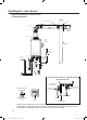
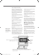
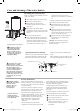
HARDWIRING
THE ELECTRICAL CONNECTIONS:
● Wiring should be carried out by a qualified
electrician in accordance with local codes.
● The water heater requires 120 VAC/60Hz and
should be properly grounded.
● DO NOT connect grounding wire to water
pipes, gas pipes, telephone cables, lightning
conductor circuits and to grounding circuit
of other equipment that carry a ground-fault
interrupter.
● An ON/OFF switch must be provided and
installed for the incoming 120VAC power.
● Wire the water heater exactly as shown
below. A wiring diagram is also found
inside of the cover panel.
● A green screw is provided in the enclosure
for a grounding connection.
● Connect the live wire to black leg wire and
the neutral wire to the white neutral wire.
WARNING: Shock
hazard line voltage is
present. Before servicing
the water heater, turn off
the electrical power to the
water heater at the main
disconnect or circuit
breaker. Failure to do so
could result in severe
personal injury or death.
CAUTION: Label
all wires prior to
disconnection when
servicing controls. Wiring
errors can cause improper
and dangerous operation.
Verify correct operation
after servicing.
WARNING: Field wiring connections and electrical grounding must comply with local codes, or
in the absence of local codes, with the latest edition of the National Electrical Code, ANSI/NFPA 70,
or in Canada, Canadian Electrical Code, CSA C22.1 Part 1.
21
31-93618 0
VERT/JAUNE
G/Y:GREEN/YELLOW,
AC
120V
O:ORANGE,ORANGE
CODE DE COULEUR
COLOR CODE
MIN BUTTON
BOUTON MIN.
G/YorG
W
BOUTON MAX.
BL
BL BL
LED
G G
MAX BUTTON
ADJUSTER BUTTON
BL
BOUTON DE RÉGLAGE
BL
1
2
3
4
5
A
FOR INDOOR,DIRECT-VENT
MODEL ONLY
POUR MODÈLE INTÉRIEUR À
ÉVENT DIRECT SEULEMENT
4 3 2
1
Y
W
R
BK BL
W
BL
R O Y
FOR DIRECT-VENT MODEL ONLY
POUR MODÈLE À ÉVENT DIRECT SEULEMENT
SW3SW2
SW1
U
2
1
S
1
3
2
W
W
1
2
3
4
I
J
H
F
W
W
2
3
4
1
B
R
Y
O
W
BR
BK
1
2
3
4
5
6
7
8
R
Y
O
W
BR
BK
1
2
3
4
5
6
7
8
C
9
R
BR
BK
BK
W
BK
W
1
2
3
4
Y
W
BK
1
23
K
SV0
SV1
SV2
SV3
W
BK
W
G/Y
GY
BK
IG
1
23456
G
FM
5
GY
W
Y
R
R
BK
BK
R
1
2
3
4
5
6
7
+
PSV
R1
R2
R3
R4
BK
BK
-
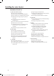
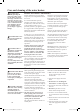
WIRING DIAGRAM
SCHÉMA DE CÂBLAGE
MOTEUR DU
VENTILATEUR
FAN MOTOR
ELECTRODE
IGNITER
FUSE(3A)
(UMC-117)
CIRCUIT BOARD
PLAQUE DE CIRCUIT
ÉLECTRODE
ALLUMEUR
ANTI-FROST HEATER
CHAUFFAGE ANTI-GIVRE
FUSIBLE(3A)
ON
MARCHE
OFF
ARRÉT
CONTACTEUR DIP 1
DIP SWITCH 1
DIP SWITCH 2
CONTACTEUR DIP 2
ON
MARCHE
OFF
ARRÉT
ÉLECTROVALVE DE DÉRIVATION D'EAU
WATER VOLUME CONTROL MOTOR
WATER BY-PASS CONTROL MOTOR
MOTEUR DE CONTRÔLE DU VOLUME D'EAU
R:RED,ROUGE
W:WHITE,BLANC
BR:BROWN,BRUN
BL:BLUE,BLEU
BK:BLACK,NOIR
GY:GRAY,GRIS
G:GREEN,VERT
Y:YELLOW,JAUNE
BK
(USC1-117)
(USC2-117)
WW
LIMITER
LIMITEUR
MOTOR
MOTEUR
LIMITER
LIMITEUR
MOTOR
MOTEUR
4
5678
GY
R
BL
SV4
BK
BK
BK
BK
1
2
3
V
T
BL
M
W
FLAME ROD 1
ÉLECTRODE DE
DÉTECTION
DE FLAMME 1
FLAME ROD 3
ÉLECTRODE DE
DÉTECTION
DE FLAMME 3
FOR INDOOR,DIRECT-VENT
MODEL ONLY
POUR MODÈLE INTÉRIEUR À
ÉVENT DIRECT SEULEMENT
RÉSISTANCE
USUALLY
DISCONNECTED
NORMALEMENT
DECONNECTE
BK
GND
GND
RESISTOR
SOLENOID VALVE 3
ÉLECTROVALVE 3
SOLENOID VALVE 2
ÉLECTROVALVE 2
ÉLECTROVALVE 1
SOLENOID VALVE 1
ÉLECTROVALVE DANS
ADMISSION DE GAZ
GAS INLET
SOLENOID VALVE 0
OVER HEAT LIMITER
LIMITEUR DE SURCHAUFFE
WATER FLOW SENSOR
D'EAU
CAPTEUR DE DÉBIT
P.G.F.R VALVE
AMBIENT AIR
THERMISTOR
D'AIR AMBIANT
THERMISTOR
DE SORTIE D'EAU CHAUDE
D'ECHANGEUR DE CHALEUR
HOT WATER OUTLET
THERMISTOR
THERMISTOR
HEAT EXCHANGER
THERMISTOR
D'ADMISSION D'EAU
THERMISTOR
WATER INLET
THERMISTOR
THERMISTOR
GAS TYPE
CIRCUIT BOARD
PLAQUE DE CIRCUIT
IMPRIMÉ DE TYPE Â GAZ
MAIN REMOTE
CONTROL
TÉLÉCOMMANDE
<<MAIN>>
BATH REMOTE
CONTROL 1
BATH REMOTE
CONTROL 2
TÉLÉCOMMANDE 1
TÉLÉCOMMANDE 2
<<BATH>> <<BATH>>
SOLENOID VALVE 4
ÉLECTROVALVE 4
GG BL BLBK R Y O
W
BR
8
BK R Y O
W
BR
8
AP15317 (10_09) DV Gas Manual 10 30 09.indd 21 11/9/2009 3:10:30 PM