
Use and Care Manual


1
!
CAUTION: The burner chamber is a sealed area. If
the inner door, lower air box or mounting plate is
removed, the respective gaskets must be replaced. This
should only be done by a qualified service technician.
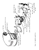
1. INSPECT SHIPMENT:
Inspect contents for possible missing or damaged compo-
nents. Refer to Figure 3. This kit includes:
1 - Inner Door Gasket
1 - Mounting Plate Gasket
4 - Speed Clips
1 - Transition Pan Gasket
2 - #8 x 1 1/4" T20 Torx Head Screws
2 - #6 Screws
2 - #8 - 32 x 3/8" Screws
2 - #8-32 x 1/4" Screw
2 - #8 - 32 Hex Nuts
4 - #10 - 32 Hex Nuts
1 - Pilot Assembly
2 - #8 x 3/4" Screws
1 - Pilot Bracket
2. ADDITIONAL INSTRUCTIONS REQUIRED:
Refer to the Use and Care Manual supplied with the water
heater for complete information on the installation, lighting
instructions, operation and maintenance of the water heater.
3. SHUT OFF THE GAS SUPPLY:
Turn off the gas supply at the main gas line. Refer to the
label located on the front of the unit above the gas valve
for instructions on "To turn Gas off to the appliance" or the
Use & Care Manual.
4. REMOVE THE JACKET DOOR:
Remove jacket door by lifting the door upward, then out-
ward.
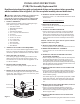
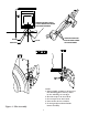
5. REMOVAL OF CONNECTIONS TO GAS VALVE:
Unscrew the pilot supply tube, the thermocouple, the burner
supply tube, and unplug the ignitor wire from the piezo
ignitor striker. Refer to Figure 1.
6. REMOVAL OF T20 TORX HEAD SCREWS:
Remove the (2) #8 x 1 1/4" T20 Torx head screws at the ends of
the Inner Door.
You will need a #20 size TORX head tool.
7. REMOVAL OF HEX NUTS:
Remove the two #8-32 hex nuts at the top and bottom cen-
ter of the inner door.
8. REMOVAL OF THE INNER DOOR:
Remove the Inner Door Assembly. If removal is difficult
you can insert a flat head screw driver between the door
and the burner assembly and pry the two apart all around
the outside area of the inner door. Grasp the burner supply
tube and remove the inner door assembly from the burner
chamber.
NOTICE: The inner door gasket must be replaced with the
supplied new inner door gasket.
9. REMOVE THE LOWER AIR BOX:
Unscrew (2) #8-32 x 3/8" screws and remove lower air box.
10. REMOVE BURNER/PILOT ASSEMBLY:
Unscrew (2) #8 x 3/4" screws and remove the burner/pilot
assembly.
11. REMOVING THE PILOT BURNER AND PIEZO
ELECTRODE ASSEMBLY:
Remove the pilot burner and piezo electrode assembly from
the pilot mounting bracket by removing (2) #8-32 x 1/4
screws that attaches it. Remove the complete pilot, ther-
mocouple and piezo electrode assembly from the mounting
plate by pulling the orange grommet from the burner access
door through the hole from the back.
12. REMOVE THE MOUNTING PLATE GASKET AND
REPLACE.
Remove the old mounting plate gasket and discard. Clean
the metal surfaces on which the old gasket was attached on
the back of the burner/pilot assembly and the front of the
burner chamber opening.
The outside edge may be scraped with a putty knife, sanded
lightly with sand paper, and washed with a light soap and
water mixture to remove the old gasket material and adhe-
sive.
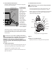
13 REMOVE PILOT MOUNTING BRACKET (If unit was
produced prior to November 2013)
Remove (2) #6 screws attaching bracket to burner and
replace with new bracket provided . Ensure that bracket is
flush to burner assembly and located properly to burner.
Refer to Figures 4 & 5.
14. REMOVE THE TRANSITION PAN GASKET AND
REPLACE.
Remove the old transition pan gasket and discard. Clean the
INSTALLATION INSTRUCTIONS
(FVIR) Pilot Assembly Replacement Kit
Read these instructions thoroughly and understand all steps and procedures before proceeding
with the installation. Refer to figures 3, 4, & 5 for an exploded assembly view and detail views.
AP14531-5 (04/15)
Pilot Supply Tube
Piezo Ignitor Wire
Thermocouple
Burner Supply Tube
Figure 1
Piezo Ignitor