
Use and Care Manual

!
CAUTION: The burner chamber is a sealed area. If
the burner access door is removed, the burner access
door gasket must be replaced. This should only be done
by a qualified service technician.
INSPECT SHIPMENT:
Inspect contents for possible missing or damaged compo-
nents. This kit includes:
Qty. 4 (four) - Tamper Resistant Screws
Qty. 1 (one) - Pilot Assembly (Pilot Burner, Piezo
Electrode, Thermopile, & Door Grommet)
Qty. 1 (one) - Pilot Assembly Attachment Screw
Qty. 4 (four) - Speed Clips
Qty. 1 (one) - Burner Access Door Gasket
Qty. 1 (one) - Installation Instructions
Qty. 1 (one) - Pilot Tube Clip
Qty. 1 (one)- Type A Piezo Adapter
(Honeywell Pilot Assembly to White-Rodgers
Control)
Qty. 2 (two)- Thermopile Adapters
TOOLS REQUIRED:
7/16” Open-end wrench
3/4” Open-end wrench
#20 Torx head tool
Phillip’s head screwdriver
Fine wire brush
Soap and water solution
Needle Nose Pliers
ADDITIONAL INSTRUCTIONS:
Refer to the Use and Care Manual supplied with the water
heater for complete information on the installation, lighting
instructions, operation and maintenance of the water heater.
1.
TURN OFF GAS TO THE APPLIANCE: Rotate the com-
bination gas control/thermostat knob counter-clockwise to
the “OFF” position.
2
REMOVE JACKET DOOR: See Figure 1 or 2.
3. DISCONNECTION OF THERMOPILE, PILOT SUPPLY
LINE, BURNER SUPPLY TUBE AND PIEZO WIRING
FROM THE COMBINATION GAS CONTROL: Locate
the thermopile connector on the combination gas control.
Carefully pull off the connector. Using a 7/16" open-end
wrench, disconnect the pilot supply line from the combination
gas control. Using a 3/4" open-end wrench, disconnect the
burner supply tube from the combination gas control. Locate
the piezo wire connector and disconnect it by pulling it apart.
See Figures 1 or 2 for the type of control your water heater is
equipped with..
NOTICE: The threads for connection of the burner supply
tube nut on LP combination gas controls are left-handed.
INSTALLATION INSTRUCTIONS
(Honeywell Pilot Assembly Replacement Kit)
Read these instructions thoroughly and understand all steps and procedures before
proceeding with the installation.
1
AP16773-2 (7-17)
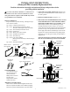
Figure 1
Honeywell Combination Gas Control
Piezo Wire
Connector
Thermopile
Connector
Burner
Supply Tube
Pilot Supply Line
Jacket Door
Speed Clips
Pilot
Assembly
Pilot Tube Clip
Pilot Attachment
Screw
T20 Torx Head Screws
Burner Access
Door Gasket
TO LIGHT PILOT:
PRESS / HOLD KNOB IN PILOT POSITION
PRESS IGNITER BUTTON UNTIL PILOT LIGHTS
RELEASE KNOB WHEN STATUS LIGHT BLINKS
OFF
PILOT
VAC
WARM
HOT
A
B
C
VERY
HOT
SCALDING RISK INCREASES
WITH HOT WATER
STATUS
PILOT
IGNITER
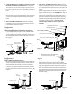
Figure 2
White-Rodgers Combination Gas Control
Piezo Wire
Connector
Thermopile
Connector
Burner
Supply Tube
Pilot Supply Line
Jacket Door
Type A Piezo Adapter
Thermopile
Adapters
Needle Nose
Pliers