
Use and Care Manual
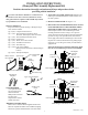

4. TAMPER RESISTANT SCREWS (USED TO SECURE
BURNER ACCESS DOOR) REMOVAL: Using a #20
Torx head tool, remove the four tamper resistant screws at
the corners of the burner access door assembly and discard
them.
5. BURNER ACCESS DOOR ASSEMBLY REMOVAL:
Grasp the burner supply tube and carefully remove the burner
access door assembly with burner assembly from the water
heater.
6. PILOT ASSEMBLY REMOVAL: Determine which pilot
assembly location your water heater has and follow the appro-
priate removal instructions as follows:
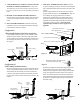
Configuration 1
(Pilot assembly mounted to the burner supply tube)
Using a Phillip’s Head Screwdriver, remove the screw which
attaches the pilot assembly to the burner supply tube and dis-
card it. Pull the orange grommet with the pilot assembly out of
the mounting hole, which is located on the burner access door.
See Figure 3.
Configuration #2
(Pilot assembly mounted to burner)
Remove the pilot tube clip from the burner supply tube and dis-
card it. Using a Phillip’s Head Screwdriver, remove the screw
which attaches the pilot assembly to the burner and discard
it. Pull the orange grommet with the pilot assembly out of the
mounting hole, which is located on the burner access door. See
Figure 4.
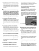
7. NEW PILOT ASSEMBLY INSTALLATION: Insert the
new pilot assembly by placing the connection ends through the
hole (combustion chamber side) on the burner access door. See
Figure 5.
Push the orange grommet into the hole of the door until it is
properly seated. See Figures 5 & 6. IMPORTANT: Take care
not to damage the orange grommet when you install it.
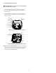
Attach the new pilot assembly to the bracket on the burner
and secure it with the new pilot assembly attachment screw
(supplied). All replacement pilot assemblies attach directly
to the burner, as shown in Figure 7. DO NOT attach
replacement pilot assembly to burner supply tube if
applicable.
Route the pilot supply line and wiring through the pilot tube
clip then attach the clip to the burner supply tube.While
holding the orange grommet in place, snug up the thermopile
wiring, pilot supply line and piezo ignitor wiring so there is
little to no to slack between the main burner and the burner.
Ensure that the fiberglass sleeving between the pilot and the
grommet is covering the lengths of the piezo electrode and
thermopile wiring.
2
Push the grommet into the burner
access door from this side.
Figure 6
View of pilot assembly
Burner
Burner Supply Tube
Figure 5
Thermopile Connector
Burner Access Door Grommet
Screw Location on Bracket
Piezo Wire
Pilot Supply Tube
Burner Supply
Tube
Pilot assembly
Pilot assembly
mounting screw
Figure 3
Figure 5
Burner
Supply
Tube
Pilot
assembly
Pilot Tube Clip
Pilot assembly
mounting screw
Pilot Tube Clip
Figure 7
Pilot Tube Clip
Figure 4