
Use and Care Manual

8. BURNER ACCESS DOOR GASKET REMOVAL AND
INSTALLATION: Remove the old burner access door gasket
from the combustion chamber and burner access door. Clean
the surfaces to which the gasket was attached. If the old gasket
was attched with an adhesive, a fine wire brush and soap and
water solution may be used to remove the old gasket material
and adhesive.
!
WARNING! DO NOT use any flammable liquids such as
gasoline, paint thinners, or solvents to remove the old gas-
ket material and adhesive (if applicable). Place the new gas-
ket on the clean and dry side (combustion chamber side) of
the burner access door. If the gasket is equipped with peel
and stick adhesive, peel off the pull away backing from the
new burner access door gasket and install the gasket on the
clean and dry side (combustion chamber side) of the burner
access door. Ensure that the gasket used for the tamper
resistant screws align with those in the burner access door.
9. INSTALLING THE BURNER ACCESS DOOR
ASSEMBLY: Remove the 4 (four) speed clips that are located
at the inner door opening attached to the combustion chamber
and discard them. Install the 4 (four) new speed clips (sup-
plied). Re-install the burner access door assembly to the water
heater. Ensure that the burner access door gasket is seated prop-
erly.
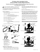
10. CONNECTION OF BURNER SUPPLY TUBE AND
PILOT SUPPLY LINE: Install the inverted flared end of
the burner supply tube into the combination gas control. Hand
thread the hex nut fitting on the burner supply tube into the
control. Ensure that the fitting is properly aligned with the
control, otherwise cross threading of the connection will occur.
Tighten the fitting using a 3/4" open-end wrench. See Figures 1
or 2 for the type of control your water heater is equipped with.
NOTICE: The threads for connection of the burner supply
tube nut on LP combination gas controls are left-handed.
Install the end of the pilot supply line into the combination
gas control. Hand thread the hex nut fitting on the pilot supply
line into the control. Ensure that the fitting is properly aligned
with the control, otherwise cross threading of the connection
will occur. Tighten the fitting using a 7/16" open-end wrench.
See Figures l or 2 for the type of control your water heater is
equipped with.
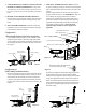
11. CONNECTION OF THERMOPILE AND PIEZO
WIRING:
For water heaters equipped with Honeywell
Combination Gas Control
Locate the thermopile connector on the pilot assembly. Using
needle nose pliers push the connector onto the Honeywell
Combination Gas Control and ensure that the connector is fully
engaged. Locate the piezo wire connector and connect it to the
piezo lead coming from the gas control. See Figure 1.
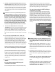
For water heaters equipped with White-Rodgers
Combination Gas Control
Locate the two thermopile adapters from the kit and using
needle nose pliers insert the female ends into the thermopile
connection of the White-Rodgers Combination Gas Control.
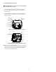
IMPORTANT: For proper installation of the thermopile
connector, the adapters must be oriented as show in Figure 8.
Push the thermopile connector of the pilot assembly onto the
thermopile adapters and ensure that the connections are correct
and the connectors are fully engaged. Locate the Type A Piezo
Adapter from the kit and connect it to the piezo lead coming
from the gas control and the piezo wire coming from the pilot
assembly.
WARNING: Failure to properly install the burner access
door assembly could result in a potentially hazardous situ-
ation resulting in death or serious injury and/or property
damage.
12. TURN ON GAS TO THE APPLIANCE: Turn on the gas
supply at the main gas supply line. Follow the “FOR YOUR
SAFETY READ BEFORE OPERATING” and “LIGHTING
INSTRUCTIONS” label located above the water heater's com-
bination gas control.
13. CHECKING FOR GAS LEAKS: With the pilot and main
burner in operation, use a soap and water solution to check for
gas leaks at the burner supply and pilot supply line connec-
tions.
NOTICE: If the soap and water solution bubbles up, there
is a leak and the fittings must be tightened and checked
again.
IMPORTANT: If the leak(s) cannot be eliminated, turn off
the gas supply to the water heater and contact the water
heater manufacturer at the phone number indicated in the
water heater's Use & Care Manual.
3
Figure 8
!
Thermopile adapters
installedd