
Rheem RTGH Owners Manual


INSTALLATION INSTRUCTIONS
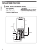
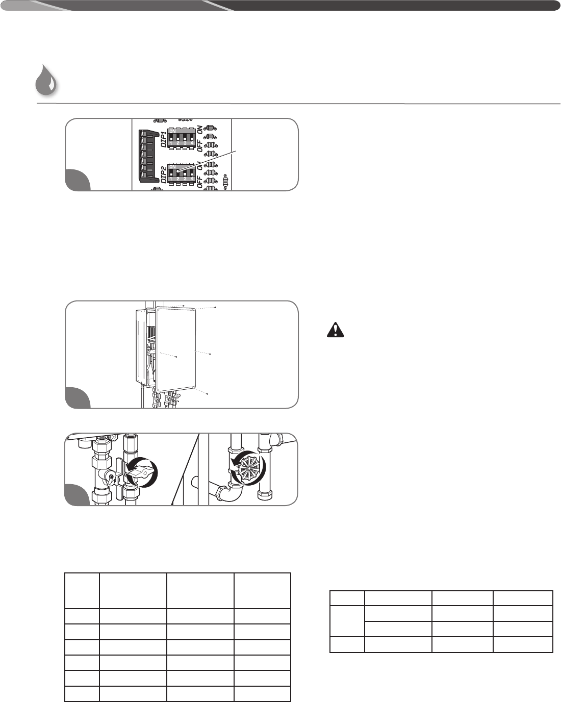
To set A-2 setting, change the second swtich on "DIP 2"
to the ON position (UP).
NOTICE:
DO NOT alter any other DIP switch settings. Please
contact technical service listed on page 26 of this use
and care manual if you have any questions of DIP switch
adjustments.
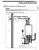
Replace the front cover panel.
Turn on the gas and water to the water heater by
opening the shut-off valves.
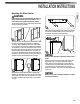
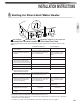
Minimum / Maximum Vent Length
(intake/outlet) each at A-2 Setting
The system will not operate if there is excessive
restriction (pressure drop) in the venting system. Use the
chart above to calculate the maximum pipe run length
with the required number of elbows (e.g., a maximum 57
ft. [17.4 m] of 2" vent pipe may be used provided there is
only one 90° elbow in the system).
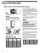
A 90° elbow is equivalent to 3 ft (0.9 m) of 2", and to 1ft.
6 in (0.5m) of 3" straight pipe. A 45° elbow is equivalent
to 1ft. 6 in (0.5 m) of 2" straight pipe, and 9ft. (0.25 m) of
3" straight pipe.
The vent termination and/or one 90 degree elbow at air
intake does not count as part of the straight pipe equivalent
when determining the total vent length.
NOTICE:
To use 3" vent pipe, an increasing adapter will be required.
WARNING:
To use Category III Stainless Steel, a proper transition part
will be required to prevent flue gas from leaking.
This water heater requires the correct DIP switch
adjustments per vent length for proper operation. Incorrect
DIP switch adjustments may cause improper water heater
operation resulting in serious injury or death.
Depending on the size of pipe that is chosen for venting
the water heater, it might be necessary to use a fitting
for stepping down in pipe size, to connect to the water
heater.
All intake and exhaust venting components must have
the same diameter size. DO NOT use a different size on
the intake and exhaust venting.
It is recommend to have a vent length as short as
possible. Input rate of the water heater decreases if there
is restriction (pressure drop) in the venting system.
The following table shows approximate input rate
reduction. Actual input rate reduction may be different at
each installation.
Venting for Direct-Vent Water Heater
6
7
Number
of 90°
Elbows
Minimum Length of
2" Straight Pipe
Maximum Length of
2" Straight Pipe
3" Pipe
1 22.0 ft (6.7 m) 57.0 ft (17.4 m) Not allowed
2 19.0 ft (5.8 m) 54.0 ft (16.5 m) Not allowed
3 16.0 ft (4.9 m) 51.0 ft (15.5 m) Not allowed
4 13.0 ft (4.0 m) 48.0 ft (14.6 m) Not allowed
5 10.0 ft (3.0 m) 45.0 ft (13.7 m) Not allowed
6 7.0 ft (2.1 m) 42.0 ft (12.8 m) Not allowed
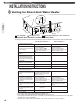
Setting Vent Size Min Vent Length Max Vent Length
A-1
3" 0% 15 - 20%
2" 5% 15 - 20%
A-2 2" 10% 20 - 25%
36
5
Dip #2 is on