INSTALLATION INSTRUCTIONS FOR UPFLOW/HORIZONTAL & DOWNFLOW INDUCED DRAFT GAS FURNACES (-)GPN/(-)GPP UPFLOW/HORIZONTAL SERIES (-)GLN DOWNFLOW SERIES 92-24161-38-03 SUPERSEDES 92-24161-38-02
Before beginning any troubleshooting procedure, complete the following installation checklist. A furnace malfunction is sometimes caused by an improper installation. By completing this checklist, the problem may be found and corrected. Make copies of the checklist and complete one for every Low Profile Furnace service call for your records. INSTALLATION CHECKLIST (Refer to this manual for specifics.
Important: All Rheem products meet current Federal OSHA Guidelines for safety. California Proposition 65 warnings are required for certain products, which are not covered by the OSHA standards. California's Proposition 65 requires warnings for products sold in California that contain, or produce, any of over 600 listed chemicals known to the State of California to cause cancer or birth defects such as fiberglass insulation, lead in brass, and combustion products from natural gas.
SAFETY INFORMATION ! WARNING USE ONLY WITH TYPE OF GAS APPROVED FOR THIS FURNACE. REFER TO THE FURNACE RATING PLATE. ! WARNING INSTALL THIS FURNACE ONLY IN A LOCATION AND POSITION AS SPECIFIED IN THE LOCATION REQUIREMENTS AND CONSIDERATIONS SECTION OF THESE INSTRUCTIONS. ! WARNING PROVIDE ADEQUATE COMBUSTION AND VENTILATION AIR TO THE FURNACE SPACE AS SPECIFIED IN THE VENTING SECTION OF THESE INSTRUCTIONS. ! WARNING COMBUSTION PRODUCTS MUST BE DISCHARGED OUTDOORS.
GENERAL INFORMATION The (-)GPN/(-)GPP/(-)GLN series furnaces are design certified by CSA for use with natural and propane gases as follows: As a Category I furnace, it may be vented vertically with type B-1 vent pipe and also may be common vented as described in these instructions. This furnace should be installed in accordance with the American National Standard Z223.1 - latest edition booklet entitled “National Fuel Gas Code” (NFPA 54) (in Canada, CSA B149.1 and .
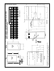
F 265/8 GAS CONNECTION 2613/16 C SUPPLY AIR 111/2 143/8 11 24 /32 E RETURN AIR /32 SIGHT GLASS 19 23 /32 17 11/4 AIRFLOW IMPORTANT: This furnace is not approved or recommended for installation on its back, with access doors facing upwards.
265/8 GAS CONNECTION 26 /16 13 ELECTRIC CONNECTION LOW VOLTAGE C 63/16 203/8 S.A. 233/8 E BOTTOM AIRFLOW SIGHT GLASS /8 5 193/4 3 5 2311/32 241/2 15 R.A. 2311/32 241/2 12 B 13 /8 19 /32 21 10(B) A 121/8 1611/32 171/2 10(A) 27 16 /32 17 /2 07 /4 /8 155/8 155/8 7 12 /8 11 1 103/8 1227/32 1 14 05 C B A Model NOTE: IN DOWNFLOW CONFIGURATION, OPTIONAL AIR CUTOUT IS NOT PERMITTED.
CLEARANCE – ACCESSIBILITY The design of forced air furnaces with input ratings as listed in the tables on the following pages are certified by CSA for the clearances to combustible materials shown in inches. See name/rating plate and clearance label for specific model number and clearance information. Service clearance of at least 24 inches is recommended in front of all furnaces. ACCESSIBILITY CLEARANCES, WHERE GREATER, MUST TAKE PRECEDENCE OVER FIRE PROTECTION CLEARANCES.
FAILURE TO PREVENT PRODUCTS OF COMBUSTION FROM BEING CIRCULATED INTO THE LIVING SPACE CAN CREATE POTENTIALLY HAZARDOUS CONDITIONS, INCLUDING CARBON MONOXIDE POISONING THAT COULD RESULT IN PERSONAL INJURY OR DEATH. DO NOT, UNDER ANY CIRCUMSTANCES, CONNECT RETURN OR SUPPLY DUCTWORK TO OR FROM ANY OTHER HEAT PRODUCING DEVICE SUCH AS A FIREPLACE INSERT, STOVE, ETC. DOING SO MAY RESULT IN FIRE, CARBON MONOXIDE POISONING, EXPLOSION, PERSONAL INJURY OR PROPERTY DAMAGE.
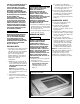
• • • • • FIGURE 5 HORIZONTAL RETURN AIR DUCT (LEFT-HAND AIRFLOW POSITION SHOWN) AIRFLOW Commercial buildings Buildings with indoor pools Furnaces installed in laundry rooms Furnaces in hobby or craft rooms Furnaces installed near chemical storage areas. Exposure to the following substances in the combustion air supply may also require OUTDOOR AIR for combustion: RETURN REAR VIEW FOUR ANGLE BRACKETS ARE SHIPPED WITH EACH UNIT THAT CAN BE INSTALLED HORIZONTALLY.
Combustion air must be free of acid forming chemicals; such as sulphur, fluorine and chlorine. These elements are found in aerosol sprays, detergents, bleaches, cleaning solvents, air fresheners, paint and varnish removers, refrigerants and many other commercial and household products. Vapors from these products when burned in a gas flame form acid compounds. The acid compounds increase the dew point temperature of the flue products and are highly corrosive after they condense.
FIGURE 8 COMBUSTION AIR FITTING – NON-ATTIC COMBUSTION AIR PULL, GPN & GPP ONLY ATTACH OPTIONAL DOUBLE ELBOW TO TOP INLET AIR OPENING TO PREVENT ACCIDENTAL BLOCKAGE OF INTAKE OPENING. THIS IS NOT A REQUIREMENT. (SEE PREVIOUS PAGE.) SINGLE ELBOW IS ALLOWED BUT MAY NOT PREVENT DEBRIS FROM BEING DROPPED INTO THE FURNACE. EXHAUST PVC DOUBLE ELBOW METAL FLUE PIPE ONLY 6" MININUM CLEARANCE #8 SCREWS #8 SCREWS 6" MIN.
FIGURE 9 OUTSIDE AIR USING A HORIZONTAL INLET & OUTLET B: Method 3, GPN and GPP only For the optimum in quiet operation, attic air may be brought directly to the furnace. IMPORTANT: In applications using Method 3 for combustion air, the attic must be ventilated by gable or soffit vents. See Figure 7. ! CAUTION COMBUSTION AIR INTAKES CANNOT BE TERMINATED OUTSIDE. DOING SO CAN CAUSE IMPROPER OPERATION OF THE FURNACE.
VENTING GENERAL INFORMATION FIGURE 11 ATTACHING TO DRAFT INDUCER COLLAR The furnace must be vented in accordance with these instructions, National Fuel Gas Code, ANSI Z223.1 and/or the Natural Gas Installation Code, CSA-B149.1 & .2 and requirements or codes of the local utility or other authority having jurisdiction.
“B-1” VERTICAL VENTING Type “B-1” vents must be installed in accordance with the terms of their listings and the vent manufacturer’s instructions. FIGURE 12 TYPICAL VENTING WITH “B-1” VENT “B-1” vents must be supported and spaced in accordance with their listings and the manufacturer’s instructions. All vents must be supported to maintain their minimum clearances from combustible material.
POWER VENT SYSTEMS EXISTING VENT SYSTEMS When vertical venting is not possible, the only acceptable method for horizontal venting is with the use of Tjernlund model GPAK-1TR or Field Controls models SWG-4R power venter. Type B vent pipe and fittings must be used. Common venting is not permitted IMPORTANT RETROFIT VENTING INSTRUCTIONS All application and installation instructions supplied with the power venter must be followed.
GAS SUPPLY AND PIPING GAS SUPPLY ! WARNING THIS FURNACE IS EQUIPPED AT THE FACTORY FOR USE ON NATURAL GAS ONLY. CONVERSION TO LP GAS REQUIRES A SPECIAL KIT AVAILABLE FROM THE DISTRIBUTOR. FAILURE TO USE THE PROPER CONVERSION KIT CAN CAUSE FIRE, CARBON MONOXIDE POISONING, EXPLOSION, PROPERTY DAMAGE, PERSONAL INJURY OR DEATH. See the conversion kit index supplied with the furnace. This index identifies the proper LP Gas Conversion Kit required for each particular furnace.
GAS PRESSURE LP CONVERSION NOx MODELS IMPORTANT: The maximum gas supply pressure to the furnace should be 10.5” w.c. for natural gas and 13” w.c. for LP gas. NOTE: For installation, see specific LP kit installation instructions. When converting furnaces equipped with NOx inserts to LP gas, remove the NOx insert assemblies. Steps for removal are listed below: Natural gas supply pressure should operate between 5" to 10.5” w.c. LP gas supply pressure should be 11” to 13” w.c.
SETTING GAS PRESSURE The maximum gas supply pressure to the furnace should be 10.5” w.c. natural gas, or 13” w.c. LP gas. The minimum supply gas pressure to the gas valve should be 5" w.c. natural gas or 11" w.c. LP gas. A properly calibrated manometer is required for accurate gas pressure measurements.
ADJUSTING OR CHECKING FURNACE INPUT ! CAUTION ELEVATIONS ABOVE 2000 FT REQUIRE THAT THE FURNACE INPUT RATE BE ADJUSTED AND THAT THE SIZE OF THE BURNER ORIFICES BE RE-CALCULATED BASED ON ELEVATION AND GAS HEATING VALUE. THE BURNER ORIFICES MAY (OR MAY NOT) NEED TO BE CHANGED. SEE THE SECTION TITLED “HIGH ALTITUDE INSTALLATIONS” OF THIS BOOK FOR INSTRUCTIONS. NATURAL GAS: The maximum gas supply pressure to the furnace should be 10.5” W.C. for natural gas.
ELECTRICAL WIRING ! FIGURE 16 ISOLATION RELAY WARNING TURN OFF ELECTRIC POWER AT THE FUSE BOX OR SERVICE PANEL BEFORE MAKING ANY ELECTRICAL CONNECTIONS. ALSO, THE GROUND CONNECTION MUST BE COMPLETED BEFORE MAKING LINE VOLTAGE CONNECTIONS. FAILURE TO DO SO CAN RESULT IN ELECTRICAL SHOCK, SEVERE PERSONAL INJURY OR DEATH. IMPORTANT: The furnace must be installed so that the electrical components are protected from water due to improper flue installation or evaporator condensate drain run-off, etc.
FIGURE 17 LINE VOLTAGE CONNECTIONS UT ELECTRONIC CONTROLS 1028-928 CONTROL BOARD I677 UT ELECTRONIC CONTROLS 1097-200 CONTROL BOARD FIELD INSTALLED OPTION ACCESSORIES FURNACE TWINNING INSTALLATIONS ELECTRONIC AIR CLEANER Electronic air cleaner line voltage power can be supplied from the screw terminal “EAC” and a line voltage neutral screw terminal on the control board. Power is on any time the blower is activated. See Figure 17. IMPORTANT: ONLY TWIN FURNACES WITH IDENTICAL CONTROL BOARDS.
FIGURE 18 UT Electronic Controls 1028-928 CONTROL BOARD, TWINNING CONNECTION -- SINGLE STAGE OPERATION a099201 23
FIGURE 19 UTEC 1028-928 CONTROL BOARD, TWINNING CONNECTION -- TWO-STAGE OPERATION a099301 24
80+ HIGH ALTITUDE INSTRUCTIONS (TABLE 8) ! CAUTION THE NATIONAL FUEL GAS CODE (NFGC) GUIDELINES SHOULD BE FOLLOWED WHEN CONVERTING THESE FURNACES FOR HIGH ALTITUDE OPERATION. 34" 80 Plus furnaces installed above 2,000 ft. require the furnace to be derated 4% per thousand feet. IMPORTANT: Factory installed orifices are calculated and sized based on a sea level Natural Gas heating value of 1075 BTU per cubic ft. NOTE: Orifices are available through your local distributor.
25.98 24.95 22.39 21.
START-UP PROCEDURE LIGHTING INSTRUCTIONS This appliance is equipped with a direct spark ignition device. This device lights the main burners each time the room thermostat (closes) calls for heat. See lighting instructions on the furnace. TO START FURNACE ! WARNING 1. BE SURE THAT THE MANUAL GAS VALVE HAS BEEN IN THE “OFF” POSITION FOR AT LEAST FIVE MINUTES. DO NOT ATTEMPT TO MANUALLY LIGHT THE MAIN BURNERS.
1. FAN SPEED* — motor runs on this speed when the thermostat is in the “FAN” position. As a consequence, some troubleshooting approaches should be modified. In particular is a common field method to test for a properly functioning limit or limit circuit. The procedure is to disconnect the limit wires from the limit(s) during steady “on” or idle (no call for heat, cool or continuous fan present). When this was done in the past, the indoor blower and inducer would turn on immediately.
AIR FLOW The importance of proper air flow over the heat exchanger cannot be over emphasized. ! FIGURE 23 TEMPERATURE RISE MEASUREMENT CAUTION IT IS IMPORTANT THAT EACH DUCT SYSTEM BE SIZED AND INSTALLED FOR THE SPECIFIC APPLICATION BY PROPERLY APPLYING THE APPROPRIATE INDUSTRY ACCEPTED STANDARD.
BLOWER PERFORMANCE DATA – (-)GLN DOWNFLOW MODELS MODEL NUMBER (-)GLNSERIES BLOWER SIZE [mm] BLOWER SPEED .1 [.02] .2 [.05] .3 [.07] .4 [.10] .5 [.12] .6 [.15] .7 [.
BLOWER PERFORMANCE DATA – (-)GPN UPFLOW/HORIZONTAL MODELS MODEL NUMBER (-)GPNSERIES BLOWER SIZE [mm] MOTOR H.P.
SAFETY FEATURES LIMIT CONTROL The high limit cut-off temperature is set at the factory and cannot be adjusted. The temperature setting prevents the air temperature leaving the furnace from exceeding the maximum outlet air temperature, which, if exceeded, will shut the furnace down. There are several reasons for a limit switch to open and almost always involve low airflow through the furnace. 1. A dirty or restricted air filter. 2. A dirty or restricted cooling coil. 3.
MAINTENANCE TABLE 9 FILTER SIZES UPFLOW FILTER SIZES AS SHIPPED ! WARNING DISCONNECT MAIN ELECTRICAL POWER TO THE UNIT BEFORE ATTEMPTING ANY MAINTENANCE. FAILURE TO DO SO CAN CAUSE ELECTRICAL SHOCK RESULTING IN SEVERE PERSONAL INJURY OR DEATH. FILTERS NOTE: (-)GPP models are not factory equipped with filters or filter rods. Filters must be field installed. Filter application and placement are critical to airflow, which may affect the heating and cooling system performance.
FIGURE 26 UPFLOW FILTER RETAINING ROD (SIDE RETURN) FILTER ROD 45-24095-01 FILTER ROD SUPPORT ANGLE AE-60520-01 FILTER SUPPORT ANGLE AE-61883-01 FILTER AND ROD ASSEMBLY CUT-OUT AND DRILL DETAIL FILTER ROD SUPPORT ANGLE AE-60520-01 FILTER SUPPORT ANGLE (SEE ANGLE DETAIL) AE-61883-01 ROD & FILTER SUPPORT ANGLE ASSEMBLY SOLID BOTTOM MAY BE ORDERED FROM THE FACTORY.
SYSTEM OPERATION INFORMATION Advise The Customer To: 1. Keep the air filters clean. The heating system will operate better, more efficiently and more economically. 2. Arrange the furniture and drapes so that the supply air registers and the return air grilles are unobstructed. 3. Close doors and windows. This will reduce the heating load on the system. 4. Avoid excessive use of kitchen & bathroom exhaust fans. 5.
FIGURE 29 TROUBLESHOOTING FLOWCHART INTEGRATED FURNACE CONTROL (IFC) TROUBLESHOOTING GUIDE WARNING HAZARDOUS VOLTAGE LINE VOLTAGE CONNECTIONS NOTE: Most failures are not due to the IFC. Double check all other possibilities, including the ground connection, before replacing the IFC. NOTE: Always verify gas valve inlet and outlet gas pressure.
FIGURE 30 FOR MODELS WITH UT ELECTRONIC CONTROLS 1028-928 INTEGRATED FURNACE CONTROL AND DIRECT SPARK IGNITION 37
FIGURE 31 FOR MODELS WITH UT ELECTRONIC CONTROLS 1027-200 INTEGRATED FURNACE CONTROL AND DIRECT SPARK IGNITION 38
CM 1004