INSTALLATION INSTRUCTIONS FOR UPFLOW/HORIZONTAL INDUCED DRAFT GAS FURNACES (-)GPN/(-)GPP SERIES 92-24161-38-01 SUPERSEDES 92-24161-38-00
Before beginning any troubleshooting procedure, complete the following installation checklist. A furnace malfunction is sometimes caused by an improper installation. By completing this checklist, the problem may be found and corrected. Make copies of the checklist and complete one for every Low Profile Furnace service call for your records. INSTALLATION CHECKLIST (Refer to this manual for specifics.
CONTENTS Safety Precautions ...................................................................................................4 Installation Check List ..............................................................................................2 General Information..................................................................................................5 Location Requirements and Considerations ............................................................5 Combustion and Ventilation Air...........
SAFETY INFORMATION ! WARNING USE ONLY WITH TYPE OF GAS APPROVED FOR THIS FURNACE. REFER TO THE FURNACE RATING PLATE. ! WARNING INSTALL THIS FURNACE ONLY IN A LOCATION AND POSITION AS SPECIFIED IN THE LOCATION REQUIREMENTS AND CONSIDERATIONS SECTION OF THESE INSTRUCTIONS. PROVIDE ADEQUATE COMBUSTION AND VENTILATION AIR TO THE FURNACE SPACE AS SPECIFIED IN THE VENTING SECTION OF THESE INSTRUCTIONS.
GENERAL INFORMATION The (-)GPN/(-)GPP series furnaces are design certified by CSA for use with natural and propane gases as follows: As a Category I furnace, it may be vented vertically with type B-1 vent pipe and also may be common vented as described in these instructions. This furnace should be installed in accordance with the American National Standard Z223.1 - latest edition booklet entitled “National Fuel Gas Code” (NFPA 54) (in Canada, CSA B149.1 and .
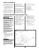
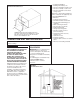
F 265/8 GAS CONNECTION 2613/16 C SUPPLY AIR 111/2 143/8 11 24 /32 E RETURN AIR IMPORTANT: This furnace is not approved or recommended for installation on its back, with access doors facing upwards.
CLEARANCE – ACCESSIBILITY The design of forced air furnaces with input ratings as listed in the tables on the following pages are certified by CSA for the clearances to combustible materials shown in inches. See name/rating plate and clearance label for specific model number and clearance information. Service clearance of at least 24 inches is recommended in front of all furnaces. ACCESSIBILITY CLEARANCES, WHERE GREATER, MUST TAKE PRECEDENCE OVER FIRE PROTECTION CLEARANCES.
FAILURE TO PREVENT PRODUCTS OF COMBUSTION FROM BEING CIRCULATED INTO THE LIVING SPACE CAN CREATE POTENTIALLY HAZARDOUS CONDITIONS, INCLUDING CARBON MONOXIDE POISONING THAT COULD RESULT IN PERSONAL INJURY OR DEATH. DO NOT, UNDER ANY CIRCUMSTANCES, CONNECT RETURN OR SUPPLY DUCTWORK TO OR FROM ANY OTHER HEAT PRODUCING DEVICE SUCH AS A FIREPLACE INSERT, STOVE, ETC. DOING SO MAY RESULT IN FIRE, CARBON MONOXIDE POISONING, EXPLOSION, PERSONAL INJURY OR PROPERTY DAMAGE.
• • • • • FIGURE 3 HORIZONTAL RETURN AIR DUCT Commercial buildings Buildings with indoor pools Furnaces installed in laundry rooms Furnaces in hobby or craft rooms Furnaces installed near chemical storage areas. Exposure to the following substances in the combustion air supply may also require OUTDOOR AIR for combustion: FOUR ANGLE BRACKETS ARE SHIPPED WITH EACH UNIT THAT CAN BE INSTALLED HORIZONTALLY. THESE BRACKETS MAY BE USED TO SECURE THE RETURN AIR DUCT TO A HORIZONTAL UNIT.
Combustion air must be free of acid forming chemicals; such as sulphur, fluorine and chlorine. These elements are found in aerosol sprays, detergents, bleaches, cleaning solvents, air fresheners, paint and varnish removers, refrigerants and many other commercial and household products. Vapors from these products when burned in a gas flame form acid compounds. The acid compounds increase the dew point temperature of the flue products and are highly corrosive after they condense.
FIGURE 6 COMBUSTION AIR FITTING – NON-ATTIC COMBUSTION AIR PULL ATTACH OPTIONAL DOUBLE ELBOW TO TOP INLET AIR OPENING TO PREVENT ACCIDENTAL BLOCKAGE OF INTAKE OPENING. THIS IS NOT A REQUIREMENT. (SEE PREVIOUS PAGE.) SINGLE ELBOW IS ALLOWED BUT MAY NOT PREVENT DEBRIS FROM BEING DROPPED INTO THE FURNACE. EXHAUST PVC DOUBLE ELBOW METAL FLUE PIPE ONLY 6" MININUM CLEARANCE #8 SCREWS #8 SCREWS 6" MIN.
FIGURE 7 OUTSIDE AIR USING A HORIZONTAL INLET & OUTLET B: Method 3 For the optimum in quiet operation, attic air may be brought directly to the furnace. NOTE: In applications using Method 3 for combustion air, the attic must be ventilated by gable or soffit vents. See Figure 5. ! CAUTION COMBUSTION AIR INTAKES CANNOT BE TERMINATED OUTSIDE. DOING SO CAN CAUSE IMPROPER OPERATION OF THE FURNACE. If attic combustion air is used, the inlet air opening at the furnace must be protected from accidental blockage.
VENTING GENERAL INFORMATION FIGURE 9 ATTACHING TO DRAFT INDUCER COLLAR The furnace must be vented in accordance with these instructions, National Fuel Gas Code, ANSI Z223.1 and/or the Natural Gas Installation Code, CSA-B149.1 & .2 and requirements or codes of the local utility or other authority having jurisdiction.
“B-1” VERTICAL VENTING Type “B-1” vents must be installed in accordance with the terms of their listings and the vent manufacturer’s instructions. FIGURE 10 TYPICAL VENTING WITH “B-1” VENT “B-1” vents must be supported and spaced in accordance with their listings and the manufacturer’s instructions. All vents must be supported to maintain their minimum clearances from combustible material.
POWER VENT SYSTEMS EXISTING VENT SYSTEMS When vertical venting is not possible, the only acceptable method for horizontal venting is with the use of Tjernlund model GPAK-1TR or Field Controls models SWG-4R power venter. Type B vent pipe and fittings must be used. Common venting is not permitted IMPORTANT RETROFIT VENTING INSTRUCTIONS All application and installation instructions supplied with the power venter must be followed.
GAS SUPPLY AND PIPING GAS SUPPLY ! WARNING THIS FURNACE IS EQUIPPED AT THE FACTORY FOR USE ON NATURAL GAS ONLY. CONVERSION TO LP GAS REQUIRES A SPECIAL KIT AVAILABLE FROM THE DISTRIBUTOR. FAILURE TO USE THE PROPER CONVERSION KIT CAN CAUSE FIRE, CARBON MONOXIDE POISONING, EXPLOSION, PROPERTY DAMAGE, PERSONAL INJURY OR DEATH. See the conversion kit index supplied with the furnace. This index identifies the proper LP Gas Conversion Kit required for each particular furnace.
GAS PRESSURE IMPORTANT: The maximum gas supply pressure to the furnace should be 10.5” w.c. for natural gas and 13” w.c. for LP gas. Natural gas supply pressure should operate between 5" to 10.5” w.c. LP gas supply pressure should be 11” to 13” w.c. This pressure must be maintained with all other gas-fired appliances in operation. NOTE: Do not exceed a gas pressure of 13” w.c. ! WARNING NEVER PURGE A GAS LINE INTO THE COMBUSTION CHAMBER. NEVER USE MATCHES, FLAME OR ANY IGNITION SOURCE FOR CHECKING LEAKAGE.
SETTING GAS PRESSURE The maximum gas supply pressure to the furnace should be 10.5” w.c. natural gas, or 13” w.c. LP gas. The minimum supply gas pressure to the gas valve should be 5" w.c. natural gas or 11" w.c. LP gas. A properly calibrated manometer is required for accurate gas pressure measurements. FIGURE 13 TYPICAL HOSE CONNECTION TO LINE PRESSURE TAP Supply Gas Pressure Measurement. A line pressure tap is on the inlet side of the gas valve. 1.
ADJUSTING OR CHECKING FURNACE INPUT 3. Time the meter to measure the time required to burn one cubic foot of gas. value of 1000 BTU per cubic feet of natural gas, and 2500 BTU per cubic feet of LP gas. NATURAL GAS: The maximum gas supply pressure to the furnace should be 10.5” W.C. for natural gas. The minimum gas supply pressure for purposes of input adjustment to the furnace should be 5” W.C. 4. Use Table 8 to determine input rate.
ELECTRICAL WIRING ! FIGURE 15 ISOLATION RELAY WARNING TURN OFF ELECTRIC POWER AT THE FUSE BOX OR SERVICE PANEL BEFORE MAKING ANY ELECTRICAL CONNECTIONS. ALSO, THE GROUND CONNECTION MUST BE COMPLETED BEFORE MAKING LINE VOLTAGE CONNECTIONS. FAILURE TO DO SO CAN RESULT IN ELECTRICAL SHOCK, SEVERE PERSONAL INJURY OR DEATH. IMPORTANT: The furnace must be installed so that the electrical components are protected from water due to improper flue installation or evaporator condensate drain run-off, etc.
FIGURE 16 LINE VOLTAGE CONNECTIONS UT ELECTRONIC CONTROLS 1028-928 CONTROL BOARD I677 UT ELECTRONIC CONTROLS 1097-200 CONTROL BOARD FIELD INSTALLED OPTION ACCESSORIES FURNACE TWINNING INSTALLATIONS ELECTRONIC AIR CLEANER Electronic air cleaner line voltage power can be supplied from the screw terminal “EAC” and a line voltage neutral screw terminal on the control board. Power is on any time the blower is activated. See Figure 16. IMPORTANT: ONLY TWIN FURNACES WITH IDENTICAL CONTROL BOARDS.
FIGURE 17 UT Electronic Controls 1028-928 CONTROL BOARD, TWINNING CONNECTION -- SINGLE STAGE OPERATION I400 a099201 22
FIGURE 18 UTEC 1028-928 CONTROL BOARD, TWINNING CONNECTION -- TWO-STAGE OPERATION a099301 23
START-UP PROCEDURE LIGHTING INSTRUCTIONS This appliance is equipped with a direct spark ignition device. This device lights the main burners each time the room thermostat (closes) calls for heat. See lighting instructions on the furnace. TO START FURNACE ! WARNING 1. BE SURE THAT THE MANUAL GAS VALVE HAS BEEN IN THE “OFF” POSITION FOR AT LEAST FIVE MINUTES. DO NOT ATTEMPT TO MANUALLY LIGHT THE MAIN BURNERS.
1. FAN SPEED* — motor runs on this speed when the thermostat is in the “FAN” position. 2. COOL — connect desired cooling speed. 3. HEAT — connect desired heating speed. 4. HEAT/COOL* — connect desired speed when heating and cooling speed are the same. *NOTE: These taps are not available on UT Electronic Controls 1097-200. ! CAUTION DO NOT CONNECT ANY MOTOR SPEEDS TO “HEAT” OR “COOL” IF YOU USE THE “HEAT/COOL” TERMINAL. DOING SO WILL DAMAGE THE BLOWER MOTOR.
AIR FLOW The importance of proper air flow over the heat exchanger cannot be over emphasized. One of the most common causes of heat exchanger failure is overheating due to low air flow. An air flow table is located inside the blower door and on the following pages. FIGURE 21 TEMPERATURE RISE MEASUREMENT IMPORTANT: Airflow must be checked at the return and the furnace outlet ahead of the coil. NOTE: Airflow external static pressure do not include filter or coil.
BLOWER PERFORMANCE DATA – (-)GPN UPFLOW/HORIZONTAL MODELS MODEL NUMBER (-)GPNSERIES BLOWER SIZE [mm] MOTOR H.P.
SAFETY FEATURES LIMIT CONTROL The high limit cut-off temperature is set at the factory and cannot be adjusted. The temperature setting prevents the air temperature leaving the furnace from exceeding the maximum outlet air temperature, which, if exceeded, will shut the furnace down. Some reasons which could cause the outlet temperature to exceed the range include: failed indoor blower, dirty filters, improper gas pressure, duct system problems, ventilation problems.
MAINTENANCE TABLE 10 FILTER SIZES UPFLOW FILTER SIZES AS SHIPPED ! WARNING DISCONNECT MAIN ELECTRICAL POWER TO THE UNIT BEFORE ATTEMPTING ANY MAINTENANCE. FAILURE TO DO SO CAN CAUSE ELECTRICAL SHOCK RESULTING IN SEVERE PERSONAL INJURY OR DEATH. FILTERS NOTE: (-)GPP models are not factory equipped with filters. Filters must be field installed. Filter application and placement are critical to airflow, which may affect the heating and cooling system performance.
FIGURE 25 FILTER RETAINING ROD (SIDE RETURN) FILTER ROD 45-24095-01 FILTER ROD SUPPORT ANGLE AE-60520-01 FILTER SUPPORT ANGLE AE-61883-01 FILTER AND ROD ASSEMBLY CUT-OUT AND DRILL DETAIL FILTER ROD SUPPORT ANGLE AE-60520-01 FILTER SUPPORT ANGLE (SEE ANGLE DETAIL) AE-61883-01 ROD & FILTER SUPPORT ANGLE ASSEMBLY SOLID BOTTOM MAY BE ORDERED AS AN OPTION FROM THE FACTORY.
IMPORTANT: Do not operate the system without filters. A portion of the dust entrained in the air may temporarily lodge in the air duct runs and at the supply registers. Any recirculated dust particles will be heated and charred by contact with the furnace heat exchanger. This residue will soil ceilings, walls, drapes, carpets, and other household articles. SYSTEM OPERATION INFORMATION Advise The Customer To: 1. Keep the air filters clean.
FIGURE 26 TROUBLESHOOTING FLOWCHART INTEGRATED FURNACE CONTROL (IFC) TROUBLESHOOTING GUIDE WARNING HAZARDOUS VOLTAGE LINE VOLTAGE CONNECTIONS NOTE: Most failures are not due to the IFC. Double check all other possibilities, including the ground connection, before replacing the IFC. NOTE: Always verify gas valve inlet and outlet gas pressure.
FIGURE 27 FOR MODELS WITH UT ELECTRONIC CONTROLS 1028-928 INTEGRATED FURNACE CONTROL AND DIRECT SPARK IGNITION 33
FIGURE 28 FOR MODELS WITH UT ELECTRONIC CONTROLS 1027-200 INTEGRATED FURNACE CONTROL AND DIRECT SPARK IGNITION 34
CM 0604