
Troubleshooting guide


25
SETTING BLOWER TIMINGS
The UT Electronic Controls control
boards have four quick connect
terminals for connecting the motor
speed leads. These are:
1. FAN SPEED* — motor runs on this
speed when the thermostat is in the
“FAN” position.
2. COOL — connect desired cooling
speed.
3. HEAT — connect desired heating
speed.
4. HEAT/COOL* — connect desired
speed when heating and cooling
speed are the same.
*NOTE: These taps are not available on
UT Electronic Controls 1097-200.
DO NOT CONNECT ANY MOTOR
SPEEDS TO “HEAT” OR “COOL” IF
YOU USE THE “HEAT/COOL”
TERMINAL. DOING SO WILL
DAMAGE THE BLOWER MOTOR.
UNUSED MOTOR WIRE TAPS MUST
BE CONNECTED TO PARKING
TERMINALS M1 AND M2 OF THE IFC,
OR PROPERLY INSULATED.
5. If heating and continuous speed are
the same, jump across “FAN” and
“HEAT” terminals.
NOTE: This does not apply to UT
Electronic Controls 1097-200 models
because the heat tap functions as the
continuous fan tap as well.
See Figures 19 and 20 for instructions for
setting the blower “OFF” timings.
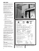
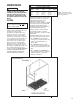
GAS FURNACE (DIRECT
DRIVE) INSTRUCTIONS FOR
CHANGING BLOWER SPEED
DISCONNECT THE ELECTRICAL
SUPPLY TO THE FURNACE BEFORE
ATTEMPTING TO CHANGE THE
BLOWER SPEED. FAILURE TO DO
SO CAN CAUSE ELECTRICAL
SHOCK RESULTING IN SEVERE
PERSONAL INJURY OR DEATH.
The blower motor is wired for blower
speeds required for normal operation
as shown.
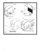
If additional blower speed taps are
available (leads connected to “M1” and
“M2” on the electronic control), speeds
may be changed if necessary to fit
requirements of the particular
installation. Reconnect the unused
motor leads to “M1” or “M2.” Check
motor lead color for speed designation.
Heating speeds should not be reduced
where it could cause the furnace air
temperature to rise to exceed the
maximum outlet air temperature
specified for the unit.
IMPORTANT: Always check air
temperature rise after changing the
heating speed for any reason or if there
are any changes to the duct system.
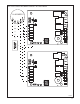
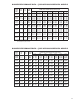
FIGURE 19
UT Electronic Controls 1028-928
BLOWER OFF TIMINGS
OFF TIME SWITCH 1 SWITCH 2
90 SEC. OFF ON
120 SEC. OFF OFF
160 SEC. ON OFF
180 SEC. ON ON
TWINSINGLE
NOTE: SWITCH 3 IS USED FOR
TWINNING APPLICATIONS.
ON
OFF
I402
WARNING
!
CAUTION
!
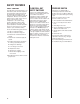
FIGURE 20
UT Electronic Controls 1097-200
BLOWER OFF TIMINGS