INSTALLATION INSTRUCTIONS 16 SEER SERIES CONDENSING UNITS 2 - 5 TONS FEATURING INDUSTRY STANDARD R-410A REFRIGERANT EQUIPPED WITH CORE SENSE CONTROL NOTE: Appearance of unit may vary. ! RECOGNIZE THIS SYMBOL AS AN INDICATION OF IMPORTANT SAFETY INFORMATION! ! WARNING THESE INSTRUCTIONS ARE INTENDED AS AN AID TO QUALIFIED, LICENSED SERVICE PERSONNEL FOR PROPER INSTALLATION, ADJUSTMENT AND OPERATION OF THIS UNIT. READ THESE INSTRUCTIONS THOROUGHLY BEFORE ATTEMPTING INSTALLATION OR OPERATION.
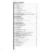
TABLE OF CONTENTS 1.0 SAFETY INFORMATION . . . . . . . . . . . . . . . . . . . . . . . . . . . . . . . . . . . . . . . . . . . . 3 2.0 GENERAL . . . . . . . . . . . . . . . . . . . . . . . . . . . . . . . . . . . . . . . . . . . . . . . . . . . . . . . 5 2.1 Checking Product Received. . . . . . . . . . . . . . . . . . . . . . . . . . . . . . . . . . . . . . 5 2.2 Application . . . . . . . . . . . . . . . . . . . . . . . . . . . . . . . . . . . . . . . . . . . . . . . . . . . 5 2.3 Dimensions . . . . . . . .
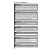
1.0 SAFETY INFORMATION ! WARNING THESE INSTRUCTIONS ARE INTENDED AS AN AID TO QUALIFIED LICENSED SERVICE PERSONNEL FOR PROPER INSTALLATION, ADJUSTMENT AND OPERATION OF THIS UNIT. READ THESE INSTRUCTIONS THOROUGHLY BEFORE ATTEMPTING INSTALLATION OR OPERATION. FAILURE TO FOLLOW THESE INSTRUCTIONS MAY RESULT IN IMPROPER INSTALLATION, ADJUSTMENT, SERVICE OR MAINTENANCE POSSIBLY RESULTING IN FIRE, ELECTRICAL SHOCK, PROPERTY DAMAGE, PERSONAL INJURY OR DEATH.
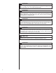
! CAUTION When coil is installed over a finished ceiling and/or living area, it is recommended that a secondary sheet metal condensate pan be constructed and installed under entire unit. Failure to do so can result in property damage. ! CAUTION THE COMPRESSOR HAS AN INTERNAL OVERLOAD PROTECTOR, UNDER SOME CONDITIONS, IT CAN TAKE UP TO 2 HOURS FOR THIS OVERLOAD TO RESET.
! WARNING THE MANUFACTURER’S WARRANTY DOES NOT COVER ANY DAMAGE OR DEFECT TO THE AIR CONDITIONER CAUSED BY THE ATTACHMENT OR USE OF ANY COMPONENTS. ACCESSORIES OR DEVICES (OTHER THAN THOSE AUTHORIZED BY THE MANUFACTURER) INTO, ONTO OR IN CONJUNCTION WITH THE AIR CONDITIONER. YOU SHOULD BE AWARE THAT THE USE OF UNAUTHORIZED COMPONENTS, ACCESSORIES OR DEVICES MAY ADVERSELY AFFECT THE OPERATION OF THE AIR CONDITIONER AND MAY ALSO ENDANGER LIFE AND PROPERTY.
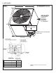
2.3 (SEE FIGURE 1) AIR DISCHARGE: ALLOW 60” MINIMUM CLEARANCE. w FIGURE 1 DIMENSIONS A-00008 AIR INLETS L (LOUVERED PANELS) ALLOW 6” MINIMUM CLEARANCE SERVICE ACCESS ALLOW 24” CLEARANCE H NOTE: GRILLE APPEARANCE MAY VARY. SEE DETAIL DIMENSIONAL DATA 16 Seer Model Size 6 24 36, 48, 60 Height “H” (in.) [mm] 273⁄8 [702] 353/8 [913] Length “L” (in.) [mm] 315⁄8 [803] 315⁄8 [803] Width “W” (in.) [mm] 315⁄8 [803] 315⁄8 [803] *NOTE: “H” dimension includes baserails and/or basepan.
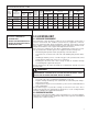
TABLE 1 ELECTRICAL AND PHYSICAL DATA – 16 SEER Electrical Physical Compressor Model Number 16 SEER Phase Frequency (Hz) Voltage (Volts) Rated Load Amperes (RLA) Locked Rotor Amperes (LRA) Fuse or HACR Circuit Breaker Outdoor Coil Fan Motor Minimum Full Load Circuit Amperes Ampacity No. (FLA) Amperes Minimum Maximum Face Area2 Rows Amperes Amperes Sq. Ft. [m ] CFM [L/s] Refrig. Per Circuit Oz. [g] Weight Net Lbs. [kg] Shipping Lbs. [kg] Rev. 12/16/2011 24 1-60-208/230 13/13 58.3 0.
NOTE: These units must be installed outdoors. No ductwork can be attached, or other modifications made, to the discharge grille. Modifications will affect performance or operation. 3.3 OPERATIONAL ISSUES • • • IMPORTANT: Locate the condenser in a manner that will not prevent, impair or compromise the performance of other equipment horizontally installed in proximity to the unit. Maintain all required minimum distances to gas and electric meters, dryer vents, exhaust and inlet openings.
4.0 REFRIGERANT CONNECTIONS All units are factory charged with Refrigerant 410A. All models are supplied with service valves. Keep tube ends sealed until connection is to be made to prevent system contamination. 5.0 TOOLS REQUIRED FOR INSTALLING & 5.0 SERVICING R-410A MODELS Manifold Sets: -Up to 800 PSIG High Side -Up to 250 PSIG Low Side -550 PSIG Low Side Retard Manifold Hoses: -Service Pressure Ratiing of 800 PSIG Recovery Cylinders: -400 PSIG Pressure Rating -Dept.
6.0 REPLACEMENT UNITS To prevent failure of a new condensing unit, the existing evaporator tubing system must be correctly sized and cleaned or replaced. Care must be exercised that the expansion device is not plugged. For new and replacement units, liquid line filter drier sould be installed and refrigerant tubing should be properly sized. Test the oil for acid. If positive, a suction line filter drier is mandatory.
TABLE 2 SUCTION LINE SIZE SUCTION LINE SIZE - OUTDOOR UNIT ABOVE INDOOR COIL R-410A System Capacity Model Line Size Connection Size (Inch I.D.) [mm] Suction Line Size Line Size (Inch O.D.) [mm] Outdoor Unit Above Indoor Coil (Cooling Only - Does not apply to Heat Pumps Total Equivalent Length - Feet [m] 25 [7.62] 2-Ton 3/4” [19.05] 3-Ton 3/4” [19.05] 4-Ton 7/8” [22.23] 5-Ton 7/8” [22.23] 5/8” [15.88] 3/4” [19.05]* 50 [15.24] 75 [22.86] 100 [30.48] 125 [38.
TABLE 3 LIQUID LINE SIZING LIQUID LINE SIZE - OUTDOOR UNIT ABOVE INDOOR COIL 2-Stage R-410A System Capacity Model Line Size Line Size Connection (Inch O.D.) Size (Inch [mm] I.D.) [mm] Liquid Line Size Outdoor Unit Above Indoor Coil (Cooling Only - Does not apply to Heat Pumps) Total Equivalent Length - Feet [m] 25 [7.6] 50 [15.24] 75 [22.86] 100 [30.48] 125 [38.1] 150 [45.72] Minimum Vertical Separation - Feet [m] (“0” means no restriction) 2-Ton 3/8” [9.53] 3-Ton 3/8” [9.53] 4-Ton 3/8” [9.
9.4 TUBING INSTALLATION Observe the following when installing correctly sized type “L” refrigerant tubing between the condensing unit and evaporator coil: ! CAUTION The filter drier is located inside the control box. The filter drier must be installed externally in the liquid line or the Warranty will be VOID! • • • • • • • • • • • If a portion of the liquid line passes through a hot area where liquid refrigerant can be heated to form vapor, insulating the liquid line is required.
! WARNING DO NOT USE OXYGEN TO PURGE LINES OR PRESSURIZE SYSTEM FOR LEAK TEST. OXYGEN REACTS VIOLENTLY WITH OIL, WHICH CAN CAUSE AN EXPLOSION RESULTING IN SEVERE PERSONAL INJURY OR DEATH. 10.0 EVACUATION PROCEDURE Evacuation is the most important part of the entire service procedure. The life and efficiency of the equipment is dependent upon the thoroughness exercised by the serviceman when evacuating air and moisture from the line set and indoor coil.
Electric resistance heaters can use CFM = volts x amps x 3.414 1.08 x temp rise Gas furnaces can use CFM = BTUH ∅T x 1.08 An air velocity meter or airflow hood can give a more accurate reading of the system CFM. 13.0 CHECKING REFRIGERANT CHARGE Charge for all systems should be checked against the Charging Chart inside the access panel cover. Before using the chart, the indoor conditions must be within 2°F of desired comfort conditions and system must be run until operating conditions stabilize (15 min.
13.2 CHARGING BY WEIGHT For a new installation, evacuation of interconnecting tubing and evaporator coil is adequate; otherwise, evacuate the entire system. Use the factory charge shown in Table 1 of these instructions or unit data plate. Note that charge value includes charge required for 15 ft. of standard size interconnecting liquid line. Calculate actual charge required with installed liquid line size and length using: 1/4” O.D. = 0.2 oz./ft. 5/16” O.D. = 0.3 oz./ft. 3/8” O.D. = 0.5 oz./ft. 1/2” O.D.
14.3 CONTROL WIRING (See Figure 2) If the low voltage control wiring is run in conduit with the power supply, Class I insulation is required. Class II insulation is required if run separate. Low voltage wiring may be run through the insulated bushing provided in the 7/8 hole in the base panel, up to and attached to the pigtails from the bottom of the control box. Conduit can be run to the base panel if desired by removing the insulated bushing.
16.0 THERMOSTAT USAGE WITH THE 16 SEER CONDENSING UNIT A two-stage cooling thermostat is required for proper unit operation. • Humidity input to the indoor air handler or furnace via the “DHM” terminal on the thermostat. Refer to System wiring for proper connections. • Compressor protection via the L terminal when the Core Sense™ module on the condensing unit is connected to the L terminal on the thermostat. 17.0 CORE SENSE The (-)AVL condensing units are equipped with a Core Sense™ diagnostics module.
2) Flash Code 3 - Short Cycling Condition: A pattern of short cycling emerges where the run time for the previous four cycles is less than three minutes each. Possible causes: High head pressure • High pressure switch is open • System overcharged • Non-condensables in system Faulty thermostat Intermittent contactor Active Thermostat Reaction: The thermostat will cycle the system ON for 5 minutes and OFF for five minutes to verify the system fault.
FIGURE 3 CORE SENSE™ DIAGNOSTICS TROUBLESHOOTING CHART Status LED Status LED Description Status LED Troubleshooting Information Green “POWER” Module has power Red “TRIP” Thermostat demand signal Y1 is present, but the compressor is not running 1. Compressor internal protector is open • Check for high head pressure • Check compressor supply voltage 2. Outdoor unit power disconnect is open 3. Compressor circuit breaker or fuse(s) is open 4. Broken wire or connector is not making contact 5.
FIGURE 3 CORE SENSE™ DIAGNOSTICS TROUBLESHOOTING CHART – CONTINUED Status LED Status LED Description Status LED Troubleshooting Information Yellow “ALERT” Flash Code 3 Short Cycling Compressor is running only briefly 1. High head pressure • Check high pressure switch if present in system • Check if system is overcharged with refrigerant • Check for non-condensable in system 3. Thermostat demand signal is intermittent 3. Time delay relay defective Yellow “ALERT” Flash Code 4 Locked Rotor 1.
TABLE 5 MAXIMUM SYSTEM CHARGE VALUES – 16 SEER 16 SEER Model Size 24 36 48 60 Compressor Model Number ZPS20K5E ZPS30K5E ZPS40K5E ZPS49K5E Charge Limit Without Crankcase Heat (1 Phase) 9.6 lbs. 12 lbs. 12 lbs. 12 lbs. 20.3 LOW AMBIENT CONTROL (LAC) This component senses compressor head pressure and shuts the heat pump fan off when the head pressure drops to approximately 220 PSIG [1516.8 kPa].
21.2 SINGLE-POLE COMPRESSOR CONTACTOR (CC) Single-pole contactors are used on all standard single phase units up through 5 tons. Caution must be exercised when servicing as only one leg of the power supply is broken with the contactor. 22.0 TROUBLE SHOOTING In diagnosing common faults in the air conditioning system, it is useful to present the logical pattern of thought that is used by experienced technicians.
22.
22.3 SUPERHEAT CALCULATION TABLE 6 TEMPERATURE PRESSURE CHART TEMP (Deg. F) R-410A PSIG -150 -140 -130 -120 -110 -100 -90 -80 -70 -60 -50 -40 -35 -30 -25 -20 -15 -10 -5 0 5 10 15 20 25 30 35 40 45 50 55 60 65 70 75 80 85 90 95 100 105 110 115 120 125 130 135 140 145 150 — — — — — — — — — 0.4 5.1 10.9 14.2 17.9 22.0 26.4 31.3 36.5 42.2 48.4 55.1 62.4 70.2 78.5 87.5 97.2 107.5 118.5 130.2 142.7 156.0 170.1 185.1 201.0 217.8 235.6 254.5 274.3 295.3 317.4 340.6 365.1 390.9 418.0 446.5 476.5 508.0 541.
22.5 GENERAL TROUBLE SHOOTING CHART ! WARNING DISCONNECT ALL POWER TO UNIT BEFORE SERVICING. CONTACTOR MAY BREAK ONLY ONE SIDE. FAILURE TO SHUT OFF POWER CAN CAUSE ELECTRICAL SHOCK RESULTING IN PERSONAL INJURY OR DEATH.
23.0 WIRING DIAGRAMS FIGURE 5 18.
FIGURE 6 18.