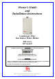
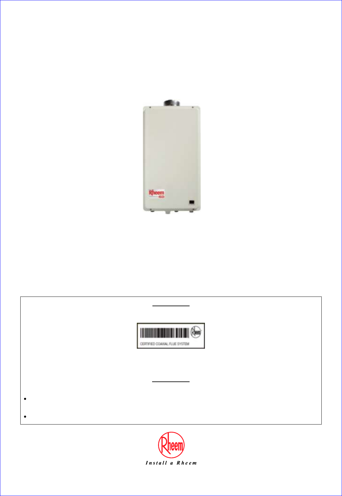
Owner’s Guide and Installation Instructions Continuous Flow Gas Indoor Water Heater 862 series 627 models INSTALLER: The ONLY suitable flue parts are certified Rheem coaxial flue components carrying the following label: DO NOT use any other type of flue parts. Carefully follow the Installation Instructions.
Warning: Upon completion of the installation and commissioning of the water heater, leave this guide with the householder or a responsible officer. DO NOT leave this guide inside of the cover of the water heater, as it may interfere with the safe operation of the water heater or ignite when the water heater is turned on. PATENTS This water heater may be protected by one or more patents or registered designs in the name of Rheem Australia Pty Ltd or Paloma Co., Ltd.
CONTENTS RESPONSIBLE OFFICER - We recommend you read pages 4 to 14. The other pages are intended for the installer but may be of interest. About Your Water Heater ............................................................................................................ 4 Water Supplies........................................................................................................................... 11 Save A Service Call ...........................................................................
ABOUT YOUR WATER HEATER WATER HEATER APPLICATION This water heater is designed for the purpose of heating potable water. Its use in an application other than this may shorten its life. MODEL TYPE ® The Rheem continuous flow gas water heater model you have chosen is for indoor installation only. This model has an extended manufacturer‟s warranty (refer to the Rheem warranty on page 55).
ABOUT YOUR WATER HEATER MAINS PRESSURE The water heater is designed for direct connection to the mains water supply. If the mains supply pressure in your area exceeds that shown on page 17, a pressure limiting valve must be fitted. The supply pressure should be greater than 140 kPa for the rated flow and performance to be achieved. HOW HOT SHOULD THE WATER BE? The water heater has a maximum preset outlet temperature setting of 82°C.
ABOUT YOUR WATER HEATER WARNING This water heater is only intended to be operated by persons who have the experience or the knowledge and the capabilities to do so. This water heater is not intended to be operated by persons with reduced physical, sensory or mental capabilities i.e. the infirm, or by children. Children should be supervised to ensure they do not interfere with the water heater. The water heater uses 240 Volt AC electrical power for operation of the control systems and the combustion fan.
ABOUT YOUR WATER HEATER PRECAUTIONS Where damage to property can occur in the event of the water heater leaking, the water heater must be installed over a safe tray. Construction, installation and draining of a safe tray must comply with AS/NZS 3500.4 and all local codes and regulatory authority requirements. The water heater must be maintained in accordance with the Owner‟s Guide and Installation Instructions.
ABOUT YOUR WATER HEATER TO TURN OFF THE WATER HEATER If it is necessary to turn off the water heater: Turn off the controllers(s) (if fitted) by pressing the on / off button. The light in the on / off button will go out and the priority light (standard controller) or the ACTIVE light (Deluxe controller), if it is on, will go out. Switch off the electrical supply at the power outlet to the water heater if there is no risk of freezing conditions occurring (refer to note below).
ABOUT YOUR WATER HEATER FROST PROTECTION The water heater has a frost protection system. The frost protection system will protect the water heater from damage, by preventing ice forming in the waterways of the water heater, in the event of freezing conditions occurring. Notes: The frost protection system will be rendered inoperable if electrical power is not available at the water heater.
ABOUT YOUR WATER HEATER HOW DO I KNOW IF THE WATER HEATER IS INSTALLED CORRECTLY? Installation requirements are shown on pages 15 to 23. The water heater must be installed: by a qualified person, and in accordance with the installation instructions, and in compliance with Standards AS/NZS 3500.4, AS 5601 or AS/NZS 5601.1, as applicable under local regulations, and all local codes and regulatory authority requirements.
WATER SUPPLIES This water heater must be installed in accordance with this advice to be covered by the Rheem warranty. This water heater is manufactured to suit the water conditions of most public reticulated water supplies. However, there are some known water chemistries which can have detrimental effects on the water heater and its operation and / or life expectancy. If you are unsure of your water chemistry, you may be able to obtain information from your local water supply authority.
SAVE A SERVICE CALL Check the items below before making a service call. You will be charged for attending to any condition or fault, which is not related to manufacture or failure of a part (refer to “Terms of the Rheem Warranty” on page 55). NO DISPLAY ON THE CONTROLLER (IF FITTED) Is the controller turned on? Press the on / off button. Is the water heater plugged in and the power outlet switched on? Is power available in the premises? Try using another electrical appliance.
SAVE A SERVICE CALL GAS BOOSTER OPERATING TOO FREQUENTLY If the water heater is installed as an in-series gas booster to a solar water heater, you may find that the water heater operates more frequently than expected. This will occur when the solar heated water temperature is lower than 2°C below a water heater preset outlet temperature setting of up to 75°C (i.e.
SAVE A SERVICE CALL CLOUDS OF WHITE ‘VAPOUR’ FROM THE FLUE TERMINAL During the heating cycle, it is not unusual to see water vapour clouds steaming from the flue terminal, particularly on cold days. This is normal operation of the water heater. PRESSURE RELIEF VALVE DISCHARGING A pressure relief valve is incorporated into the water heater controls. This valve protects the water heater, by allowing water to escape, in the event of excessive pressure build up in the waterways.
INSTALLATION – WATER HEATER THIS WATER HEATER IS FOR INDOOR INSTALLATION ONLY. THIS WATER HEATER IS NOT SUITABLE FOR POOL HEATING. Check the water heater is suitable for the gas type available. (refer to the rating label on the water heater) INSTALLATION STANDARDS The water heater must be installed: by a qualified person, and in accordance with the installation instructions, and in compliance with Standards AS/NZS 3500.4, AS 5601 or AS/NZS 5601.
INSTALLATION – WATER HEATER This water heater must be installed vertically upright with the water, gas and power connections on the underside, pointing toward the floor. The back of the water heater can be either against a wall or supported by a frame. Note: The water heater must be well secured to the wall or frame using two fasteners each at the top and bottom of the unit (refer to page 22 for mounting hole positions and weight of the water heater).
INSTALLATION – WATER HEATER MAINS WATER SUPPLY Where the mains water supply pressure exceeds that shown in the table below, an approved pressure limiting valve that does not have non return valve characteristics (such as an RMC PSL series valve) is required and should be fitted as shown in the installation diagram (refer to page 24). 27 Model Relief valve setting 1750 kPa Max. mains supply pressure 1000 kPa Min.
INSTALLATION – WATER HEATER HOT WATER DELIVERY This water heater can deliver water at temperatures which can cause scalding. It is necessary and we recommend that a temperature limiting device be fitted between an 862 series water heater and the hot water outlets in any ablution and public areas such as a bathroom, ensuite or public amenities, to reduce the risk of scalding.
INSTALLATION – WATER HEATER Where a temperature limiting device is installed adjacent to the in-series gas booster, the cold water line to the temperature limiting device can be branched off the cold water line either before or after the isolation valve and pressure limiting valve to the solar storage tank, but it MUST BE before the non return valve prior to an open circuit direct system.
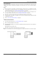
INSTALLATION – WATER HEATER CIRCULATED HOT WATER FLOW AND RETURN SYSTEM A Rheem 862 627 model continuous flow water heater can be installed as part of a circulated hot water flow and return system in a building. Notes: the preset outlet temperature setting of the water heater must be set to at least 60°C. Water should not be circulated from a water heater with a temperature setting of less than 60°C.
INSTALLATION – WATER HEATER Circulated Hot Water Flow and Return Continuous Flow Gas Water Heater LEGEND LEGEND from solar storage tank Circulated Hot Water Flow and Return In-series Gas Booster as part of a Solar Water Heater Installation LEGEND REDUCING HEAT LOSSES The hot water line from the water heater and the pipe work between the solar storage tank, if one is installed, and the in-series gas booster must be insulated in accordance with the requirements of AS/NZS 3500.4.
INSTALLATION – WATER HEATER DIMENSIONS AND TECHNICAL DATA 351 240 331 130 MOUNTING HOLES 2x TOP 2x BOTTOM 131 Ø127 Ø127 17 672 650 49 21 GAS CONNECTION HOT WATER OUTLET POWER LEAD CONNECTION 53 707 38 763 10 to 40 COLD WATER INLET 132 127 POWER LEAD CONNECTION GAS CONNECTION 5 HOT WATER OUTLET 240 107 86 COLD WATER INLET 28 ELECTRONIC CONTINUOUS FLOW 862 627 GAS WATER HEATERS INTERNAL - 862, 864, 866 SERIES litres / min627 MODELS 16.
INSTALLATION – WATER HEATER TYPICAL INSTALLATION – INDOOR LOCATION 23
CONNECTIONS – PLUMBING All plumbing work must be carried out by a qualified person and in compliance with the Standard AS/NZS 3500.4 and all local codes and regulatory authority requirements. All gas work must be carried out by a qualified person and in compliance with the Standard AS 5601 or AS/NZS 5601.1, as applicable under local regulations, and all local codes and regulatory authority requirements.
CONNECTIONS – PLUMBING PIPE SIZES The pipe sizing for hot water supply systems should be carried out by persons competent to do so, choosing the most suitable pipe size to ensure adequate flow for each individual application. Reference to the technical specifications of the water heater and local regulatory authority requirements must be made. To achieve true mains pressure operation, the cold water line to the water heater should be the same size or bigger than the hot water line from the water heater.
FLUEING SECONDARY FLUE A secondary flue must be installed with an indoor water heater to discharge combustion products to outside the building. The water heater MUST ONLY be installed with certified Rheem coaxial flue components carrying the label opposite. DO NOT use any other type of flue parts. Where more than one water heater is installed, each water heater must be individually flued using certified Rheem coaxial flue components. A common flue system MUST NOT be used.
FLUEING COMPONENTS A complete flue system is comprised from the following components.
FLUEING FLUE TERMINAL LOCATION The water heater must be located to ensure that the location of the flue terminal complies with the requirements of AS 5601 or AS/NZS 5601.1, as applicable under local regulations. As a guide the following requirements are extracted from the Gas Installations Standard. The distances are measured along the wall from the flue penetration. Horizontal Flue Terminal Location At least 300 mm between the top of the flue terminal and the eaves.
FLUEING FLUE LENGTHS Maximum Flue Length The system will not operate if there is excessive restriction (pressure drop) in the flueing system. The maximum length of a secondary flue, with no bends, between the water heater and the flue terminal is 13.5 m. To determine the maximum length of flue for an installation, reduce the maximum length of 13.5 m: by 1.5 m for every 90° bend, and by 0.75 m for every 45° bend. A secondary flue may have a combination of 90° bends and 45° bends.
FLUEING Condensate Trap and Condensate Drain Line Where the installation requires a Condensate Trap and condensate drain line: 1. Remove the clamp and rubber cap from the condensate drain spigot on the water heater flue outlet assembly. 2. Locate the Condensate Trap in a suitable position adjacent to the water heater. The loop of the condensate trap MUST BE below the spigot of the condensate drain section to ensure proper drainage. Secure to the wall with the pipe saddle supplied.
FLUEING HORIZONTAL FLUE RUNS There are a number of basic installation requirements which must be followed for a flue installation incorporating horizontal flue runs. Failure to observe these precautions can lead to the premature failure of the flue system and / or water heater. The flue must be installed with the seam of the inner flue toward the top of the installation. A horizontal section of flue must be installed with a gradient of 20 mm per metre (1 in 50 or 1° fall) of horizontal run.
FLUEING Typical Installation Horizontal Terminal with Multiple Vertical and Horizontal Sections Typical Installation Vertical Flue Typical Installation Vertical Terminal with Vertical and Horizontal Sections 32
FLUEING HORIZONTAL FLUE INSTALLATION Horizontal Flueing – Directly Behind Water Heater This method of flue installation is used where the secondary flue is to penetrate and terminate immediately behind the wall on which the water heater is mounted. Do not plumb the water heater prior to this type of flue installation, as the water heater (if mounted) requires to be removed from the wall prior to the final installation of the flue.
FLUEING Note: Steps 10 to 14 can only be conducted whilst the water heater is off the wall. 10. Connect the 90° Bend (PN 295118) to the water heater flue outlet so it is orientated behind the water heater. Fit the end of the bend down over the water heater flue outlet as far as it will go. Ensure there is a minimum 35 mm and maximum 42 mm overlap, the rubber seal on the inner flue is well seated and the bend is fully engaged on the water heater flue outlet.
FLUEING Horizontal Flueing – Extended Flue Run Notes: Ensure each flue component is fully engaged and the rubber seal on the inner duct is well seated at each joint. Each flue component is supplied with screws to connect to the adjacent flue component. The screws are located in a bag taped to the outside of the flue component.
FLUEING 4. Carefully remove the template inserted as the middle pages of this installation instructions booklet. 5. Align the top of the circular template with the mark on the wall. 6. Cut along the middle of the bold circle marked “Cut Line”. It may be convenient to tape the template to the wall. Mark the pilot hole through the centre of the template and scribe around the template onto the wall. The scribed circle should be 150 mm in diameter. 7. Remove but DO NOT DISCARD the template.
FLUEING 17. Once the flue is assembled and penetrating the wall, install the Horizontal Terminal and secure the termination to the flue using the sheet metal screws provided. Note: If the flue terminal position is more than 1800 mm above a safe working surface, then suitable equipment will be required to enable safe access to fit the flue terminal. Alternatively, the flue terminal may be fitted to the flue assembly prior to the assembly penetrating the wall. 18.
FLUEING VERTICAL FLUE INSTALLATION Suitable flashing (not supplied) is required to waterproof the roof penetration. Notes: Ensure each flue component is fully engaged and the rubber seal on the inner duct is well seated at each joint. Each flue component is supplied with screws to connect to the adjacent flue component. The screws are located in a bag taped to the outside of the flue component.
FLUEING 8. Fix a Wall Bracket after each transition to a vertical run. This is to prevent vertical loading on the bends and offsets. 9. Support vertical sections of flue at a distance no greater than 2 m using a Wall Bracket (PN 295128). Note: The Wall Bracket can be used to support vertical sections of flue from a ceiling by rotating the legs through 90°. 10. Install an Adjustable Straight Length (PN 295127) if a special length is required between offsets or changes in direction of the flue.
FLUEING MULTIPLE WATER HEATER FLUE INSTALLATION Where multiple water heaters are installed, each water heater must be individually flued to the outside. A common flue system MUST NOT be used. For a multiple unit installation, the water heater is certified for installation with zero clearance between adjacent water heaters.
FLUEING MULTIPLE WATER HEATER CONDENSATE TRAP AND CONDENSATE DRAIN LINE INSTALLATION Depending upon the type of installation, it may be necessary to install a Condensate Trap and condensate drain line to each water heater. Refer to “Draining the Condensate” on page 29. The drain line from each Condensate Trap may be: drained separately to a discharge point, or manifolded together with a single drain line running to a discharge point.
FLUEING Warning: Failure to fill with water may cause flue gasses to escape through the condensate trap. The condensate trap should be regularly checked to ensure it is filled with water, replenishing when required. Notes AS/NZS 3500.4 section 5.12 is used as a guide in preparing the following drainage recommendations. As the condensate is mildly acidic, copper tube and fittings must not be used as they will corrode. Use UPVC (Unplasticised Polyvinyl Chloride) or PE (polyethylene) piping.
CONNECTIONS – ELECTRICAL All electrical work and permanent wiring must be carried out by a qualified person and in accordance with the Wiring Rules AS/NZS 3000 and all local codes and regulatory authority requirements.
MULTIPLE INSTALLATIONS A multiple installation of 27 litre gas water heaters on a single manifold is possible, using a parallel plumbing arrangement, where large volumes of hot water are required. It is good practice, but not essential, to install ® the water heaters in an Equa-Flow plumbing arrangement. The installation may operate on a dead leg system or a circulated flow and return system.
MULTIPLE INSTALLATIONS Refer to the diagram on page 45 for installation and plant layout details. PRESSURE REDUCING VALVE COMMISSIONING PROCEDURE The pressure reducing valves must be set and commissioned for each water heater so the water heaters will turn on and off in sequence when the flow rate increases or decreases to a particular rate.
MULTIPLE INSTALLATIONS To set and commission the pressure reducing valves: 1. Commissioning: Commission each of the water heaters prior to setting the pressure reducing valve on the cold (or solar preheat) branch to the water heater (refer to “Commissioning” on page 47). 2. Turn on services: Turn on the water, gas and electricity to the water heaters. 3. Locking screw: Loosen the locking screw on each SYR valve with a flat bladed screw driver. 4.
COMMISSIONING All water heaters are tested and adjusted before dispatch from the factory, however further adjustments may become necessary because of local conditions. Note: If this water heater is installed as part of a multiple installation, i.e. in a bank of water heaters, it will be necessary to isolate the other water heaters and commission the water heaters one at a time. However, all the water heaters will need to be operating during the checking of the gas inlet pressure.
COMMISSIONING Gas Inlet Test Point Pressure To check the gas inlet pressure: 1. Close any hot taps and ensure the burners are not operating. 2. Close the gas isolation valve at the gas inlet to the water heater. 3. Locate the gas inlet test point on the gas connection to the water heater. 4. 5. Remove the test point screw and washer from the test point orifice. Connect the manometer. Open the gas isolation valve fully at the gas inlet to the water heater.
COMMISSIONING BURNER GAS PRESSURE It is necessary to check the burner gas pressure at both the minimum and maximum operational settings. To check and if necessary adjust the operational gas pressures, the electrical supply to the water heater must be switched on, the burners ignited and hot water must be flowing from a hot tap. Warning: The removal of the front panel will expose 240 volt wiring. Take care not to touch wiring terminals.
COMMISSIONING Notes: If the burners extinguish and error code 11 or 12 starts to flash on the LED display: release the MIN and adjuster buttons close the hot tap clear the error code (refer to “Clearing Error Code” on page 50) recommence the procedure from Step 8. If the adjuster button is released before Step 13, clear any error code (if displayed) and recommence the procedure from Step 8.
COMMISSIONING PRESET OUTLET TEMPERATURE SETTING The factory preset outlet temperature setting of the water heater is: 862 series 60°C 60°C 70°C for a single water heater as part of a Multipak system as part of a Commpak system If a temperature controller is connected to the water heater, this will override the preset outlet temperature setting and the maximum temperature setting will be: Maximum Outlet Temperature 862 series Kitchen controller connected 60°C Bathroom controller only connected 50°C
COMMISSIONING TO CHECK OR ADJUST THE PRESET OUTLET TEMPERATURE SETTING The temperature settings will be displayed on the LED display. The preset outlet temperature settings are: 862 series 38°C, 40°C, 42°C, 43°C, 45°C, 50°C, 55°C, 60°C, 65°C, 70°C, 75°C, 82°C It is necessary to have the electrical supply to the water heater switched on during stages of checking or adjusting the preset outlet temperature setting procedure. Warning: The removal of the front panel will expose 240 volt wiring.
COMMISSIONING TO TURN OFF THE WATER HEATER If it is necessary to turn off the water heater on completion of the installation, such as on a building site or where the premises is vacant, then: Turn off the controllers(s) (if fitted) by pressing the on / off button. The light in the on / off button will go out and the priority light (standard controller) or the ACTIVE light (Deluxe controller), if it is on, will go out.
DRAINING THE WATER HEATER To drain the water heater: Turn off the water heater (refer to “Turn Off The Water Heater” on page 53). Open a hot tap (preferably the shower outlet). Unscrew the two drain plugs, one each at the cold water inlet and hot water outlet, on the underside of the water heater. Water will drain from the water heater. When water stops flowing from the water heater, close the hot tap.
RHEEM CONTINUOUS FLOW GAS WATER HEATER WARRANTY – AUSTRALIA ONLY CONTINUOUS FLOW GAS WATER HEATER 862 627 MODELS 1. THE RHEEM WARRANTY – GENERAL 1.1 This warranty is given by Rheem Australia Pty Limited ABN 21 098 823 511 of 1 Alan Street, Rydalmere New South Wales, the supplier of Rheem continuous flow gas water heaters, manufactured by Paloma Co., Ltd., a world leader in water heater technology and manufacture. 1.
RHEEM CONTINUOUS FLOW GAS WATER HEATER WARRANTY – AUSTRALIA ONLY CONTINUOUS FLOW GAS WATER HEATER 862 627 MODELS 3. WHAT IS COVERED BY THE RHEEM WARRANTY FOR THE WATER HEATERS DETAILED IN THIS DOCUMENT 3.