Owner’s Guide and Installation Instructions Rheem Commpak® CP02-CP06 Commercial Hot Water Systems This water heater must be installed and serviced by a qualified person. Please leave this guide with a responsible officer.
Please read this manual prior to installing this product, it contains all the necessary technical and installation information that will be required by the contactor to correctly install & commission this system. This product must be installed & commissioned in accordance with the Rheem installation instructions, AS/NZS 5601, AS/NZS 3500.4, the relevant electrical & local authorities’ requirements. Operational design of this Hot Water System is protected by Australian Patent No: 2007201101.
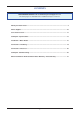
CONTENTS RESPONSIBLE OFFICER - We recommend you read pages 4 to 12. The other pages are intended for the installer but may be of interest. About your water heater ............................................................................................................. 4 Water Supplies........................................................................................................................... 10 Save A Service Call ...........................................................................
ABOUT YOUR WATER HEATER The Rheem Commpak is a bank of two, three, four, five or six continuous flow water heaters (CFWH), factory manifolded in parallel complete with multi-speed pump/s, temperature sensors and a controller. All components are factory assembled on a lightweight frame suitable for either wall (2 to 3 water heaters) or floor (2 to 6 water heaters) mounting. This water heater is designed for the purpose of heating potable water. Its use in an application other than this may shorten its life.
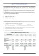
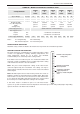
ABOUT YOUR WATER HEATER COMMPAK – MODELS AVAILABLE & TECHNICAL DATA CPE02 & CPI02 Commpak Model CPE03 & CPI03 CPE04 & CPI04 CPE05 & CPI05 CPE06 & CPI06 Approx Weight N x pumps 1P 2P 1P 2P 1P 2P 1P 2P 1P 2P Wall Mount kg 110 120 135 145 NA NA NA NA NA NA Floor Mount kg 120 130 150 160 220 230 245 255 270 Wall Mount (WM) Floor Mounting Frame (FMF) Standby Pump Water Supply Pressure 280 standard standard N/A N/A N/A optional optional standard standard standa
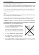
ABOUT YOUR WATER HEATER HOTTER WATER INCREASES THE RISK OF SCALD INJURY This water heater can deliver water at temperatures which can cause scalding. We recommend and it may be required by regulations that an approved temperature limiting device be fitted into the hot water piping to ablution, bathing and public areas when a Commpak water heater is installed. This will keep the water temperature below the maximum permitted by AS/NZS 3500.4 to these areas.
ABOUT YOUR WATER HEATER PRECAUTIONS Where damage to property can occur in the event of the water heater leaking, the water heater must be installed over a safe tray. Construction, installation and draining of a safe tray must comply with AS/NZS 3500.4 and all local codes and regulatory authority requirements. The water heater must be maintained in accordance with the Owner’s Guide and Installation Instructions.
ABOUT YOUR WATER HEATER TO TURN OFF THE WATER HEATER If it is necessary to turn off the water heater: x Switch off the electrical supply at the circuit breaker isolating switch to the water heater if there is no risk of freezing conditions occurring (refer to note below). x Close the gas isolation valve at the inlet to the water heater. x Close the cold water isolation valve at the inlet to the water heater. x Close the hot water return isolation valve.
ABOUT YOUR WATER HEATER FROST PROTECTION The water heater has a frost protection system. The frost protection system will protect the water heater from damage, by preventing ice forming in the waterways of the water heater, in the event of freezing conditions occurring. Notes: x The frost protection system will be rendered inoperable if electrical power is not available at the water heater.
WATER SUPPLIES This water heater must be installed in accordance with this advice to be covered by the Rheem warranty. This water heater is manufactured to suit the water conditions of most public reticulated water supplies. However, there are some known water chemistries which can have detrimental effects on the water heater and its operation and / or life expectancy. If you are unsure of your water chemistry, you may be able to obtain information from your local water supply authority.
SAVE A SERVICE CALL Check the items below before making a service call. You will be charged for attending to any condition or fault, which is not related to manufacture or failure of a part (refer to “Terms of the Rheem Warranty” on page 71). COLD WATER FROM THE HOT TAP x Is the continuous flow water heater plugged in and is the power at the isolating switch on? x Is power available in the premises? Try using another electrical appliance.
SAVE A SERVICE CALL ERROR CODE The water heater provides a diagnostic error code in the event of an interruption to its operation. The error code is displayed on the OK MONITOR on the front of the water heater as a numerical value. If an error code appears: x Close the isolation valve at the outlet of the CFWH and unplug the electrical supply to the CFWH. x Check the gas isolation valve at the gas inlet to the CFWH is fully open.
COMMPAK – SPECIFICATIONS DESIGN BASIS One or two water regulation pumps maintain the hot water supply at mains pressure over the Commpak’s design capacity. Pumps are plumbed to the water inlet of the continuous flow water heaters (CFWH) to overcome friction losses inherent within the CFWH. Pumps to provide (if required) an adjustable flow rate for the circulation of water throughout the heated water reticulation system, so as to maintain a consistency of temperature and pressure throughout.
COMMPAK - SPECIFICATIONS PLUMBING & HOT WATER PIPING INSULATION x Complete cold water & hot water piping; valves & fittings all in accordance with AS/NZS3500.4:2003 x Hot Water Piping Insulation details: x Closed cell PE foam clad with a reinforced UV resistant foil facing, suitable for outdoor usage Operating temperature to 105ºC Rated ‘R’ Value of 1.0 or greater Compliance In accordance to AS/NZS3500.4:2003, Amendment 1: 2005; Section 8.2.
INSTALLATION – WATER HEATER THIS WATER HEATER IS FOR OUTDOOR OR INDOOR INSTALLATION, MODEL DEPENDANT. THIS WATER HEATER IS NOT SUITABLE FOR POOL HEATING. Check the water heater is suitable for the gas type available. (refer to the rating label on the water heater) INSTALLATION STANDARDS The water heater must be installed: x by a qualified person, and x in accordance with the installation instructions, and x in compliance with Standards AS/NZS 3500.4, AS 5601 or AS/NZS 5601.
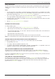
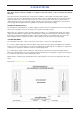
INSTALLATION – WATER HEATER OUTDOOR INSTALLATION If outdoors a secondary flue is not required. The water heater must not be installed indoors or in a confined space. The water heater must be located to ensure that the location of the flue terminal complies with the requirements of AS 5601 or AS/NZS 5601.1, as applicable under local regulations. As a guide the following requirements are extracted from AS 5601. The distances are measured along the wall behind the water heater.
INSTALLATION – WATER HEATER FROST PROTECTION The water heater has a frost protection system. The frost protection system will protect the water heater from damage, by preventing ice forming in the waterways of the water heater, in the event of freezing conditions occurring. The frost protection system will be rendered inoperable if electrical power is not available at the water heater.
INSTALLATION – WATER HEATER HOT WATER DELIVERY This water heater can deliver water at temperatures which can cause scalding. It is necessary and we recommend that a temperature limiting device be fitted into the hot water piping to any ablution and public areas such as a bathroom, ensuite or public amenities when a Commpak water heater is installed to reduce the risk of scalding.
CONNECTIONS - PLUMBING SITE LOCATION External Systems - Recommended 800mm access clearance from horizontal flue outlets Internal Systems - Recommended 600mm access clearance. Refer: Australian Standard Gas Installations AS/NZS5601 for further requirements. x Secure to wall or secure to the floor as appropriate. Consult with site structural engineer for any specific securing requirements. x Connect both cold water & hot water piping / valves and fittings as per the requirements of AS3500.
CONNECTIONS - ELECTRICAL All electrical work and permanent wiring must be carried out by a qualified person and in accordance with the Wiring Rules AS/NZS 3000 and all local codes and regulatory authority requirements. The water heater will only operate on a sine wave at 50 Hz. Devices generating a square wave cannot be used to supply power to the water heater. HOT WATER SYSTEM CONTROLLER x x Power supply: 240V/1Ph/50Hz Power Supply to the controller.
This page is intentionally blank 21
COMMPAK SINGLE PUMP - MAJOR ITEMS LISTING (CPE03 SHOWN) INTERNAL COMMPAK DUAL PUMPS - MAJOR ITEMS LISTING(CPI03 SHOWN) 22
COMMPAK – MAJOR ITEMS LISTING Refer to Photographs (Pages 22& 24); Major Items Listings / Identification (Pages 24 & 25) and External & Internal Commpak General Drawings (Pages 2826 & 29). Item No. Description Function P&EES Part No’s.
COMMPAK – MAJOR ITEMS LISTING Refer to Photographs (Pages 22& 23); Major Items Listings / Identification (Pages 24 & 25) and External & Internal Commpak General Drawings (Pages 26 & 29). Item No. Description Function P&EES Part No’s This assembly performs 3 functions 1. If hot water outlet pressure is less than coldwater inlet pressure (demand exceeds design capability), assembly allows coldwater flow from inlet to outlet, to maintain mains water pressure.
COMMPAK INTERNAL SINGLE PUMP – GENERAL ARRANGEMENT 26
COMMPAK INTERNAL DUAL PUMPS – GENERAL ARRANGEMENT 27
COMMPAK EXTERNAL SINGLE PUMP – GENERAL ARRANGEMENT 28
COMMPAK EXTERNAL DUAL PUMPS – GENERAL ARRANGEMENT 29
COMMPAK - COMMISSIONING All water heaters are tested and adjusted before dispatch from the factory, however further adjustments may become necessary because of local conditions. COMMPAK – INITIAL CHECKS 1. Check that the power supply to the system controller(Item #1) is switched OFF. 2. Check that an adequate water supply is available to the Commpak hot water system. Water supply pressure shall not exceed 800kPa. 3.
COMMPAK - COMMISSIONING GAS INLET TEST POINT PRESSURE To check the gas inlet pressure, select the CFWH at the furthest point in the manifold as the test unit: 1. Ensure the burners are not operating, by turning off the power to the Commpak. 2. Close the gas isolation valve at the gas inlet to the CFWH. 3. Locate the gas inlet test point on the gas connection to the CFWH. 4. 5. Remove the test point screw and washer from the test point orifice. WASHER Connect the manometer.
COMMPAK - COMMISSIONING Warning: The removal of the front panel will expose 240 volt wiring. Take care not to touch wiring terminals. Note: If the Commpak is using 872627 or 862627 model CFWH and is installed as an in-series gas booster for a solar water heater, then the temperature of the water entering Commpak must be at least 2°C below the water heater preset outlet temperature setting. Otherwise the gas burners will not ignite and the test point gas pressures cannot be measured. 1.
COMMPAK - COMMISSIONING Notes: x x If the burners extinguish and error code 11 or 12 starts to flash on the LED display: release the MIN and adjuster buttons close the CFWH isolation valve clear the error code (refer to “Clearing Error Code” on page 33) recommence the procedure from Step 7. If the adjuster button is released before Step 12, clear any error code (if displayed) and recommence the procedure from Step 7.
COMMPAK - COMMISSIONING PRESET OUTLET TEMPERATURE SETTING The factory preset outlet temperature setting of the water heater is: x 70°C as part of a Commpak system It is usually not necessary to check or adjust the factory preset outlet temperature setting of the water heater, unless the customer or application has a particular requirement for this to be done.
COMMPAK - COMMISSIONING TO CHECK OR ADJUST THE PRESET OUTLET TEMPERATURE SETTING The temperature settings will be displayed on the LED display. The preset outlet temperature settings are: x 872/862 series 38°C, 40°C, 42°C, 43°C, 45°C, 50°C, 55°C, 60°C, 65°C, 70°C, 75°C, 82°C It is necessary to have the electrical supply to the water heater switched on during stages of checking or adjusting the preset outlet temperature setting procedure.
COMMPAK - COMMISSIONING TO TURN OFF THE WATER HEATER If it is necessary to turn off the water heater on completion of the installation, such as on a building site or where the premises is vacant, then: x Switch off the electrical supply at the isolating switch to the Commpak (refer to note below). x Close the gas isolation valve at the inlet to the Commpak. x Close the cold water, hot water flow and building return isolation valves at the inlet to the Commpak.
COMMPAK - COMMISSIONING COMMPAK – START-UP CHECKS System Pump/s Warning: Dry running of the Pump/s will result in permanent damage and is not covered under the Rheem warranty 1. Before turning 240VAC power on to the hot water system controller ensure the following checks are undertaken. 2. Check & confirm pump/s speed (Item #5A, factory set on number 3). Note: Read and comply with the instructions as specified on the TAG tied to end of power lead. 3.
COMMPAK - COMMISSIONING 4. Advise customer to check strainers after 1 week usage. Continue to check strainers on a weekly basis until they inspect clean. Continue to check strainers on a monthly basis until they inspect clean. Continue to check strainers on a quarterly basis until they inspect clean. Thereafter check every six (6) months. 5. Re-instate Commpak by repeating steps 1 to 8 on page 37 6. Fill in commissioning sheet (page 41) 7.
COMMPAK - COMMISSIONING COMMPAK – FAULT FINDING PROCEDURE FAULT: Hot Water System not operating as expected Possible Causes Description & Recommended Corrective Action Check system controller – Is the LCD temperature display ON x No Check controller isolator is turned ON.
COMMPAK - COMMISSIONING Possible Causes Description & Recommended Corrective Action Refer Pump Manual Pages 42- 51 for additional Information Pump Fault CFWH Fault Note: NOTE: If Pump is faulty isolate pump electrically & close valve No. #16. Commpak will operate as per Multipak (Hot water on demand but no return flow) until pump can be replaced.
COMMPAK - COMMISSIONING COMMPAK – COMMISSIONING SHEET Customer : Project & Address: Package Details: Installation OK Comments Overall Installation? Installation Requirements: Individual Water Heaters Co-axial Flueing Compliance to AS/NZS 5601 and AS/NZS 3500.4 is mandatory Refer: Rheem Owner’s Guide & Installation Instructions Models 862627 for fluing requirements. Ventilation Requirements? Compliance to AS/NZS 5601 is mandatory Fuel: Natural Gas / LPG Natural Gas: 1.13 Minimum & Up to 3.
COMMPAK - COMMISSIONING COMMPAK – PUMP MANUAL 42
COMMPAK - COMMISSIONING 43
COMMPAK - COMMISSIONING 44
COMMPAK - COMMISSIONING 45
COMMPAK - COMMISSIONING 46
COMMPAK - COMMISSIONING 47
COMMPAK - COMMISSIONING 48
COMMPAK - COMMISSIONING 49
COMMPAK - COMMISSIONING 50
COMMPAK - COMMISSIONING 51
COMMPAK - COMMISSIONING COMMPAK – SYSTEM CONTROLLER - MODEL UP-TCM-01 HOT WATER CONTROL MODULE OUTLET 60 degC 10:54 am PUMP RUN HIGH TEMP. LOW TEMP. T1 - O/C T1 - S/C SPARE SPARE PUMP L/OUT T2 - O/C T2 - S/C ALARM EXIT ACTIVE TO MUTE STROBE: Press & hold Alarm Mute for 3 seconds. TO DOUBLE MUTE: Press Alarm Mute twice. All alarms will be ignored for 5 minutes. TO TEST ALARM: Press and hold LED Test for 3 seconds. Alarm will activate for 5 sec. ALARM MUTED ALARM MUTE ALARM RESET L.E.D.
COMMPAK - COMMISSIONING COMMPAK – SYSTEM CONTROLLER – SPECIAL FEATURES x Powered from 85 to 260v AC x All connections to Module are pluggable with all field wiring on one side of module.
COMMPAK - COMMISSIONING COMMPAK – SYSTEM CONTROLLER - OPERATION TEMPERATURE SENSORS x The module can cater for three different types of thermistors/sensors. x Refer to the diagram for jumper settings. x Sensor T1 is assigned to the return water. sensor T2 is assigned to the outlet water. x The default display shows outlet temperature, if dual temperatures are selected then both the outlet and return temperatures are displayed.
COMMPAK - COMMISSIONING x The low temperature LED will flash during the timing process. x Relay outputs are affected if set to low temp, temp fault or common fault. LOW TEMPERATURE LOCK-OUT x The low temperature lock-out can be set to either of the two temperature sensors T1 or T2. x Individual ON and OFF temperature thresholds are provided. x A time delay of 1-99 minutes is provided. x The output can be configured as a follower or latched.
COMMPAK - COMMISSIONING PUMP CONTROL x The Control page provides additional control functions. x In the single pump controller, the only relevant parameters are the MRT and clock control. x The remaining functions pertain to pump alternation in dual pump systems. x Pump run option determines if two pumps are permitted to run together. The lead pump can be fixed as pump 1 or pump 2, or set to alternate. x Pump alternation can be time based from 1-24 hours, or set at up to two fixed clock times.
COMMPAK - COMMISSIONING LCD BACKLIGHT: The LCD is provided with LED backlighting. The backlight operation can be set to manual or automatic, within the DISPLAY page of the Menu System. In Manual mode the backlight turns on whenever a button is pressed and remains on for X seconds as set in the Backlight On Time. Its range is 10 to 99 seconds. If set to 10 seconds then the Backlight will remain on permanently. In the automatic mode the backlight turns on for any button or alarm operation.
COMMPAK - COMMISSIONING DISPLAY OPTIONS: Within the DISPLAY page of the Menu System, are display options for the LCD. This information will be displayed unless a fault message needs to be displayed. The display will rotate through all current fault messages at a 3 second refresh rate. There are four options as follows: x Temp & Time: Outlet Temperature and Time of day will be displayed.
COMMPAK - COMMISSIONING x Once the display is showing a data item, pressing the UP or DOWN button will move through the available items. x If a particular mode is disabled, then items relating to that mode will not be displayed. x Press EXIT go back one step, or repeat again to exit altogether. x Note that while in this mode, controller operation is unaffected. SET-UP MODE: This mode is to configure the controller to your application.
COMMPAK - COMMISSIONING COMMPAK – SYSTEM CONTROLLER – PRESETS/SET-UP MODE SELECTION RANGES PAGE SUB-PAGE 1 - TYPE 2 - PARAMETERS 2.1 - UV SYSTEM 2.2 - RESERVED 2.3 - HIGH TEMP. 2.4 - LOWTEMP. 2.5 - LOWTEMP L/OUT 2.6 - TEMP CONTROL 2.7 - RELAYS 2.8 - CLOCK 3 - CONTROL 4 - PUMP STATUS 5 - DISPLAY 6 - INFORMATION 7 - FAULT LOG VIEWFAULTS ITEM OPTIONS 1.1- Hot Water Controller SIngle Pump Hot Water Controller, Dual Pump Hot Water Controller Disable, Enable N/Open.
COMMPAK - COMMISSIONING COMMPAK – SYSTEM CONTROLLER – SPECIFICATIONS Power Supply: 100-250v AC, 50Hz Module Load: xx mA max xx mA min Volts Free Contacts: Programmable as Normal or Fail-Safe. Programmable Relays RL3, RL4 and RL5 Rated at 240v AC, 2 amp. Display Indicators/Display: 4 x 3mm Superbright LEDs. 6 x 3mm Bi-Colour LED Contactor Relays: Pump 1 and Pump 2 Contactor/Pump Relays. Rated at 240v AC 10 amp, 3 amp 0.7pf.
COMMPAK - COMMISSIONING COMMPAK – SYSTEM CONTROLLER – FAULT/STATUS MESSAGES: x Initialising Eeprom: Controller has rebooted, and loading all default settings into Eeprom. x T1 Sensor Fault: T1 (return water) sensor is faulty, refer to LED for o/c or s/c fault indication. x T2 Sensor Fault: T2 (return water) sensor is faulty, refer to LED for o/c or s/c fault indication. x High Temp Fault: High Temperature Fault Alarm. x High Temp.
COMMPAK - COMMISSIONING COMMPAK – SYSTEM CONTROLLER – MODULE BLOCK DIAGRAM: CONNECTION NOTES: All terminations on the module are pluggable. For ease of Module replacement, each connector can be withdrawn, ensuring that cable connections are not transposed. Ensure the external alarm output current limits are not exceeded. The volts free contacts are rated at 240v AC, but be aware of its presence if using some for volts free monitoring.
COMMPAK - COMMISSIONING COMMPAK – SYSTEM CONTROLLER – TEST SHEET 64
COMMPAK - COMMISSIONING 65
COMMPAK - COMMISSIONING SYSTEM CONTROLLER – TIMED OPERATION TIMED OPERATION Example: An office building is only manned between the hours of 8:00AM and 6:00PM Monday to Friday This can be set as: Outside these set hours, the controllers display will show ‘SLEEP MODE’ to indicate the system is ready but disabled. When in ‘SLEEP MODE’ all temperature related alarm outputs are disabled (LED indication remains active).
COMMPAK - COMMISSIONING COMMPAK – SINGLE PUMP WIRING SCHEMATIC 67
COMMPAK - COMMISSIONING COMMPAK – SINGLE PUMP LAY-OUT & MATERIAL SCHEDULE 68
COMMPAK - COMMISSIONING COMMPAK – DUAL PUMPS WIRING SCHEMATIC 69
COMMPAK - COMMISSIONING COMMPAK – DUAL PUMPS LAY-OUT & MATERIAL SCHEDULE 70
RHEEM CONTINUOUS FLOW GAS WATER HEATER WARRANTY – AUSTRALIA ONLY CONTINUOUS FLOW GAS WATER HEATER COMMPAK MODELS CP02 – CP06 1. THE RHEEM WARRANTY – GENERAL 1.1 This warranty is given by Rheem Australia Pty Limited ABN 21 098 823 511 of 1 Alan Street, Rydalmere New South Wales. 1.2 Rheem offer a trained and qualified national service network who will repair or replace components at the address of the water heater subject to the terms of the Rheem warranty.
CONTINUOUS FLOW GAS WATER HEATER COMMPAK MODELS CP02 – CP06 3. WHAT IS COVERED BY THE RHEEM WARRANTY FOR THE WATER HEATERS DETAILED IN THIS DOCUMENT 3.