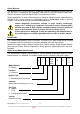
SERVICE INSTRUCTIONS 18, 20,24, 26L Integrity Electronic Gas Continuous Flow Water Heater TM031 R Reevviissiioonn:: B B P Puubblliisshheedd:: FFeebbrruuaarryy 0088 871018 871020 871024 871024-B 871024-C 871026 871026-B 1
Contents Introduction ................................................................................................................................... 3 Water Heater Model Identification................................................................................................ 3 Preset Temperature Adjustment .................................................................................................. 4 Wiring Diagram - Models with Mechanical Bypass ..............................................
Safety Warning The purpose of this service manual is to provide sufficient information to allow a person with the skills as required by the Regulatory Authorities to carry out effective repairs to a Rheem Continuous Flow Gas Water Heater in the minimum of time. Safety precautions or areas where extra care should be observed when conducting tests outlined in this service manual are indicated by print in bold italics and/or a warning symbol. Take care to observe the recommended procedure.
Preset Temperature Adjustment It is possible to choose a preset outlet water temperature setting when remote controllers are not fitted. The water heater comes factory set at 55ºC on 871 series models. Voltages up to 240 volts will be present within the water heater, take care not to touch wiring terminals. Use an insulated tool when operating the DIP switch or MIN and MAX buttons. To adjust the preset temperature: 1. Remove the front cover from the water heater. 2.
Wiring Diagram - Models with Mechanical Bypass TM031 Integrity 18, 20, 24, 26L Service Instructions REV: B D.O.I: February 2008 This document is stored and maintained electronically by 5 Service.
Wiring Diagram - Models with Solenoid Operated Bypass 6
Sequence of Operation Refer to „Sequence of Operation Component Diagram‟ on page 9 to view components shown in brackets e.g. (1) 1. When a hot water tap (1) is opened, cold water (or preheated water if a solar preheater is installed) enters the water heater and passes through the Water Flow Sensor (3) and Heat Exchanger (19).
Specifications Model 871018 871018 871020 871020 871024 871024-B 871024-C 871024 871024-B 871024-C 871026 871026-B 871026 871026-B Specification Max hourly gas cons.-MJ/Hr Min hourly gas cons.-MJ/Hr Min inlet wtr pressure-kPa Max inlet wtr pressure-kPa Min inlet gas pressure(kPa) Max inlet gas pressure(kPa) Natural 157 24 140 1000 1.13 3.5 LPG 157 24 140 1000 2.75 3.5 Natural 157 24 140 1000 1.13 3.5 LPG 157 24 140 1000 2.75 3.5 Natural 188 22 140 1000 1.13 3.5 LPG 188 22 140 1000 2.75 3.
Sequence of Operation Component Diagram 1 2 3 4 5 6 7 8 9 10 11 12 13 14 15 16 17 18 19 20 21 22 23 24 25 26 27 Hot Water Tap Bypass Control Valve Water Flow Sensor Inlet Water Temperature Thermistor Combustion Chamber Thermistor Outlet Water Temperature Thermistor Water Flow Servo Motor Water Filter (Strainer) Gas Inlet Solenoid Valve Gas Solenoid Valve 1 Gas Solenoid Valve 2 Gas Solenoid Valve 3 PGFR Valve Nozzle Burner Igniter Igniter Electrode Flame Sensor Heat Exchanger Over Temperature Limiter Exhaus
Anti-Frost Heater Circuit Models with an „F‟ in the model number have an anti frost heater circuit e.g. 871024NF-B. The anti-frost heaters are wired in series and operate independently from the water heater. The 18 and 20 litre models have a 58-watt anti-frost system. The 24 and 26 litre models have an 82-watt anti-frost system.
Note: The parts lists shown on pages 64 - 75 are for current 871026-B and 871024-C model heaters; superseded part numbers for 871024 and 871026 model heaters are not shown therein however they are listed in the following tables.
Anti-frost heater A, Pt Nº 31-71644-00 (item 705) Anti-frost heater B, Pt Nº 31-71643-00 (item 706) Anti-frost thermostat, Pt Nº 20-57072-00 (item 714) Transformer (item 783) Old Part Number WH0020073 / New Part Number 31-71646-00 This part may be connected to existing wiring utilising electrical BP connectors otherwise in addition to the transformer it will also be necessary to replace: Connecting Cord, Pt Nº 31-71641-00 (item 784) Power Cord, Pt Nº 31-76652-00 (item 780) Power Filter, Pt Nº 31-71642-00 (i
In addition to the signal loom it will also be necessary to replace: Inlet thermistor, Pt Nº 20-64773-00 (item 717) Heat Exchanger thermistor, now part of the signal loom Pt Nº 31-76655-00 (item 758) Outlet thermistor, Pt Nº 20-64774-00 (item 713) Overheat Limiter, Pt Nº 31-79562-00 (item 701) Flow Sensor, Pt Nº 20-43805-00 (item 723) Heat Exchanger Thermistor (item 715) The heat exchanger thermistor is now part of the signal loom (item 758).
Overheat Limiter (item 701) Old Part Number 54-02730-00 / New Part Number 31-79562-00 In addition to the overheat limiter it will also be necessary to replace: Signal Loom, Pt Nº 31-76655-00 (item 758) Ambient air thermistor, now part of the signal loom Pt Nº 31-76655-00 (item 758) Heat Exchanger thermistor, now part of the signal loom Pt Nº 31-76655-00 (item 758) Inlet thermistor, Pt Nº 20-64773-00 (item 717) Outlet thermistor, Pt Nº 20-64774-00 (item 713) Flow Sensor, Pt Nº 20-43805-00 (item 723) Flow Sen
In-series Gas Boosting Temperature controllers must not be fitted if this water heater is installed as part of a solar water heater system because water at a temperature much higher than the controller setting can be delivered. If a solar pre-heater has been installed to an existing Integrity water heater installation then a solar bypass valve or a comparator must be fitted at this water heater and any controllers, if fitted, must be disconnected and removed.
In-series Gas Boosting Integrity Solar Hiline Installation Note: This plumbing diagram is also applicable to standard model heaters fitted with a comparator. For more information on comparators refer to page 17.
Paloma Solar Bypass Valve RMC Solar Bypass Valve Inlet water from solar water heater Hot water outlet Note: If a 821020, 821024, 821024-B or 821026 model heater is replaced with an 821020B, 821024-C or 821026-B model heater and the existing 871020, 871024, 871024-B or 871026 heater is used as an in-line booster and has a solar bypass valve fitted, the solar bypass valve must be removed and the plumbing connections remade directly to the Integrity inlet and outlet water connections (refer to diagrams on p
Removing a Solar Bypass Valve and Installing a Comparator 1. Ensure power and water to the water heater is isolated. 2. Remove the front cover (refer to component procedure 1 on page 52). 3. Locate the 2 pin wiring plug in the wiring loom to the cold sensor mounted on the water body (refer to fig 1) and disconnect. 2 pin cold sensor wiring plug disconnected Cold sensor Fig 1 4.
In-series Gas Boosting 871020, 871024, 871024-B & 871026 Solar Loline Installation Note: For 871020, 871024 & 871024-B and 871026 model heaters fitted with a comparator refer to diagram on page 15. For more information on comparators refer to page 17. In-series Gas Boosting 871020, 871024, 871024-B & 871026 Solar Hiline Installation Note: For 871020, 871024 & 871024-B and 871026 model heaters fitted with a comparator refer to diagram on page 15. For more information on comparators refer to page 17.
Tempering Valves On 871 series models where a tempering valve is fitted and there is not a separate untempered line for the kitchen or laundry areas, the Kitchen temperature controller will not be able to display temperatures above 55oC and the delivered water temperature at the tap will be that set by the tempering valve, which will be no hotter than 55oC.
Standard Controller Controller „In use‟ light Controller „priority‟ light Water temperature adjustment buttons Controller display panel (water temp or water volume) Controller ON / OFF button Water volume button Note: If one or more controllers are installed, at least one must be on for the water heater to operate. If all controllers are off the water heater will only deliver cold water.
(up button) The up button increases the temperature setting. (down button) The down button decreases the temperature setting. Water volume button (Kitchen controller only) – This feature enables an alarm to sound when a set volume of water has flowed through the water heater (refer to notes below). Water volume notes: The water volume function is designed to warn, by a beeping sound, that a certain volume of water has been delivered from the water heater.
How to Fault Find When conducting fault finding techniques it is important to understand that the same error code with a different sequence number can be displayed at different points during the operational sequence of the water heater. It is important to determine where the fault occurred in relationship to the operational sequence of the water heater before commencing fault finding tests, as the tests may differ even though the same error code can be displayed.
About the Operational Flow Charts The Operational Flow Charts provide information on the start up sequence and, in the event a failure occurs at any point of the start up sequence, what error code will be displayed. When a fault occurs, an error code and sequence number will alternate in the LED display. The Sequence Number Table below indicates the section of the operational sequence (boxed numbers on the left hand side of the operational flow chart) where the fault occurred.
Operational Flow Charts 1 & 2 Operation Flow Chart 1 & 2 Plug In Power On 1 Error code cleared Isolate Power On /Off lamp Off Remote controller display off Bath fill operation B Initial check normal ? NO Functional problem on gas type circuit board Communication problem between remote controller and the heater 82 Flashing 76 Flashing YES Remote controller switched on Remote controller switched off Fan Off 10 seconds later On /Off lamp On Remote controller display on Fan motor current detect
F 11 12 Operational Flow Chart 3 F1 G.I.S.V (SVO ) on Igniter on Igniter off P .G .F.R Valve off S .V . 2 (SV 2) off 13 S.V .1 (SV 1) on 14 S .V . 2 (SV 2) on 10 P.G .F.R Valve on S .V . 1 (SV 1) off 0.1 seconds later G .I.S .V (SVO ) off P .G .F.R Valve off First ignition trial ? Flame NO Detected ? 3 seconds later Leakage> than 0.1uA YES 16 YES G .I.S .V (SVO ) off S .V. 1 (SV 1) off S .V. 2 (SV 2) off S .V. 3 (SV 3) off NO [on ] displayed C.I. on Igniter off P.G .F.
Operation Flow Chart 4 & 5 Hot tap closed Post Purge Shut Down Function Water flow sensor off G.I.S.V (SVO) off or [S.V. 1-3 (SV1-3) off] Check gas cut off function by alternating the closing order of gas valves SVO and SV1-3 at each shut down P.G.F.R Valve at minimum Fan motor at minimum LED off Fan motor at minimum C.I. Off YES 4 8 seconds later Flame current detected less than 0.1uA? NO YES G.I.S.V (SVO) off or [S.V. 1-3 (SV1-3) off] S.V. 1-3 (SV1-3) failure G.I.S.
Error Codes The following table outlines the error codes, possible causes and diagnostic tests to conduct. More detailed diagnosis is outlined in the fault finding and operational flow charts.
Diagnostic Test Points Refer to wiring diagram, page 5, for connector and wiring positions.
Maintenance Information Information relating to both the current and past operation of the water heater can be obtained from the memory; this information is referred to as the maintenance information. The table below details the information that can be recalled from the memory i.e. to view the current temperature being measured by the outlet thermistor select 5Y, refer to page 31 for the procedure to display maintenance information.
Displaying Maintenance Information Voltages up to 240 volts will be present within the water heater, take care not to touch wiring terminals. Use an insulated tool when operating the DIP switch or MIN and MAX buttons. At the Water Heater 1. Remove the front panel from the water heater. 2. Using an insulated tool, turn DIP SWITCH 1 on (refer to figure 1). 3. Use the MIN button to change the left digit (0→1etc.
Resetting Error Codes Most Error Codes can be reset by shutting off the hot water flow and turning the controllers (if fitted) off and then on again. It may also be necessary to isolate and restore the power. Where controllers are not fitted it may be necessary to turn the power off at the water heater to clear the error code. Voltages up to 240 volts will be present within the water heater, take care not to touch wiring terminals. Use an insulated tool when operating the DIP switch or MIN and MAX buttons.
Fault Diagnosis Sequence (Fault Finding Chart G) NOTE: If the power has been disconnected from the water heater wait 30seconds from power restoration before commencing this procedure.
Fault Finding Chart 1 Voltages up to 240 volts will be present within the water heater, take care not to touch wiring terminals. Use an insulated tool when operating the DIP switch or MIN and MAX buttons. Power Supply 1 Is 240 volts AC Present at the power point? No power supply. Check household wiring. NO YES Is Test 1 240 volts AC Present at the transformers primary winding? NO Cordset open circuit? - replace. Inline fuses open circuit – replace.
Fault Finding Tests 1 – 4 Components will be “Live” when conducting tests, exercise caution. Test 1 Test 2 Measure the voltage at the connector plug to the transformer primary winding with a multimeter set on the AC voltage scale. If the voltage is between 230V and 250V the cord set and inline fuses are ok. Measure the voltage at the connector plug from the transformer secondary winding with a multimeter set on the AC voltage scale. If the voltage is between 90V and 110V the transformer is ok.
Fault Finding Chart 2 TM031 Integrity 18, 20, 24, 26L Service Instructions REV: B D.O.I: February 2008 This document is stored and maintained electronically by 36 Service.
Fault Finding Tests 5 – 8 Isolate power before removing connector plugs Test 5 Test 6 Unplug connector B from the PCB and measure Unplug connector K from the PCB. Restore the resistance of the Over Heat Limiter Assembly. power and check if error code 79 is displayed Resistance should be between 50kilo-ohms and within 30 seconds. 500 kilo-ohms. Isolate power when conducting resistance tests.
Fault Finding Chart 3 Ignition and Temperature Control 3 Is error code 24 displayed? Operation switch malfunction YES Is error code 24 shown on error code display also? NO Test 7 Also when Min/Max button is YES pressed? YES Replace the remote controller. Release the Min/Max buttons and re-open a hot tap.
Fault Finding Tests 9 – 13 Isolate power when conducting resistance tests.
Fault Finding Chart 3.1 3.1 Test 11 Is flame detection signal in maintenance information 00? False flame detection malfunction Is error code 72 displayed? YES NO Replace the PCB assembly. NO Clean or replace the combustion chamber front panel assembly. YES Ignition failure or cross light failure Is error code 11 YES displayed? Did the burner ignite? YES Is there any voltage at the flame sensors? Test 12 NO Replace the PCB assembly. NO YES Did the igniter spark? NO YES 3.
Fault Finding Chart 3.2 3.2 Is gas available? NO Open the gas isolation valve. YES Is the gas pressure correct at the burner test point? NO Test 14 Is there voltage at the gas inlet solenoid valve? NO Replace the PCB assembly. NO Replace the proportional gas flow regulating valve assembly.
Fault Finding Tests 14 – 22 Isolate power when conducting resistance tests. “Live” components present during voltage tests, exercise caution. Tests 14, 15, 18, 19, 20 and 21 NOTE: Measure the voltage with connector L plugged into PCB Solenoid Valve 14 GISV 1 18 2 3 Normal Voltage Test Point 9 Yellow 10 Black 3 Red 10 Black 4 White 10 Black 5 Blue 10 Black Diagnostic Point Test Solenoid Valve 11 15 GISV 13 14 1 19 15 2 Normal Resistance Test Point 0.8kilo-ohms to 2.
Fault Finding Charts 3.3 and 3.5 3.3 Flame failure Is error code 12 displayed? Are the max and min burner pressures correct? YES NO NO Is error code 10 or 99 displayed? YES Abnormal combustion Adjust maximum and minimum burner pressures. 3.2 Clean the heat exchanger, combustion chamber, fan and air intake. For error code 99 reset the PCB by following the procedure in the section on „Error Codes‟.
Fault Finding Chart 3.6 3.6 Water flow servo malfunction Is error code 65 displayed? Test 30 Is the bypass solenoid open circuit? Integrity temp set below 46 degrees. Integrity temp set above 46 degrees. Mechanical bypass (models without -B or -C suffix in model number) YES Replace water body assembly. NO Note: the bypass solenoid is activated only if the set temperature is below 46 degrees.
Fault Finding Tests 23 – 28 Test 23 - Diagnostic Point 18 Test 24 - Diagnostic Point 18 Conduct test with water flowing Conduct test with water flowing Test Point Connector H Measured Value Test Point Connector H Measured Value 2 White - 8 Black DC8 – 16V 7 Red - 8 Black DC8 – 16V Components will be “Live” when conducting tests, exercise caution Test 25 - Diagnostic Point 18 Test Point Connector H 6 Green - 8 Black Test 28 - Diagnostic Point 3 Measured Value Conduct test with water flowing
Fault Finding Chart 3.7 3.7 Outlet water temp too high Is error code 16 displayed ? YES *Is the Is the Integrity used as YES Integrity outlet temp an in-series gas set at 60ºC ? Booster? *871018, 871020 871024, 871024-B 871026 model heaters are unsuitable for use as in-series gas boosters YES **Is the Integrity inlet water temp > 77ºC? NO NO Set the Integrity outlet temp to 60ºC **Error code16 will occur if the Integrity heats the water to 20º above the set point 3ºC.
Fault Finding Chart 3.8 3.8 Fan current detecting circuit failure Error code 79 displayed. Was Error code 79 displayed prior to opening the hot tap? YES 2 Replace the PCB assembly. Note: only replace the PCB assembly if error code 79 is displayed during combustion. NO Fault Finding Tests 29 – 31 Test 29 - Diagnostic Point 3 Components will be “Live” when conducting tests, exercise caution Conduct test with water flowing Measure the voltage between 9 Brown and 10 Black on connector B.
Fault Finding Charts 4 and 4.1 4 Is the Integrity used as an in-series gas booster? YES Are Controllers fitted? 4.1 Read maintenance information 1y Is the water flow more than 3 litres/min? 1y = Water flow detected by water flow sensor NO NO YES Test 28 Is the voltage between NO connector B10 & 11 normal? YES Controllers must not be fitted when an Integrity is used as an in-series gas booster. Remove controllers. Replace the PCB assembly.
Fault Finding Chart 4.2 4.2 871020 & 871026, 871024 & 871024-B Is a solar bypass valve fitted? YES Is a comparator fitted? YES 871024 871024-B have a or models&must have models a solar must bypass valve solar bypass valve or awhen comparator fitted a comparator fitted used as an inwhen an in-series gas booster. seriesused gasas booster. If a solar bypass Ifvalve a solar bypass valve are and fitted, a comparator and a comparator remove the are fitted, remove the solar bypass valve.
Fault Finding Chart 4.3 4.3 Is the preheated water to the solar bypass valve > 57ºC? YES Water will be diverted by the solar bypass valve. No water will flow through the Integrity therefore it will not operate. Normal operation. YES Replace the PCB assembly.
Fault Finding Chart 5 Fault Finding Tests 32 and 33 Test 32 Components will be “Live” when conducting test, exercise caution Conduct test with water flowing Measure the voltage at the 3 pin connector located between the water flow sensor and the comparator. Measure the voltage between the brown and black wires at this connector. Voltage should be between DC2 – 5V. Test 33 Remove flow sensor turbine by following component replacement procedure 21 on page 58. The flow sensor turbine should spin freely.
Adjustment Adjustment of the burner pressure will not overcome problems associated with poor supply pressure or incorrect gas supply pipe sizing. Minimum Burner Gas Pressure 1. 2. 3. 4. 5. Remove the front panel from the water heater. Remove burner test point screw and fit manometer. Turn on the remote controller (If fitted). Open a hot tap slowly, to achieve the minimum flow rate at which the burners will ignite.
Burner Change-Over Assembly: (Procedure 2) 1. Remove the front panel. Refer to Procedure 1. 2. Disconnect the wiring plug from each of the solenoid valves. (Note which plug goes to each valve) 3. Remove the screw retaining the ignition pack to the Burner Change Over Assembly. 4. Remove the six screws retaining the Burner Change Over Assembly. Four from the Combustion Chamber Front Panel and two from the Proportional Gas Flow Regulating Valve Assembly. 5. Remove the Burner Change Over Assembly. 6.
Proportional Gas Flow Regulating Valve: (Procedure 7) 1. Remove the front panel and Burner Change Over Assembly. Refer to Procedures 1 and 2. 2. Disconnect the gas supply pipe from the gas inlet connection. 3. Remove the three screws from the gas inlet connector and withdraw the connector and o-ring from the base of the water heater. 4. Carefully remove the Proportional Gas Flow Regulating Valve from the water heater. 5.
Anti-Frost Heaters: (Procedure 10) Note: Only models with an „F‟ in the model number are fitted with anti-frost heaters e.g. 871024NF. 1. Remove the front panel. Refer to Procedure 1. Heat Exchanger and Hot Water Outlet Connection Heaters 1. 2. 3. 4. Disconnect connector plugs at the sensing thermostat and at the power cord. Remove Flange (item 445) to release the Hot Water Outlet Anti-frost Heater. Unclip the 2 anti-frost heaters from the heat exchanger (Note the positions of both).
Ignition Pack Replacement: (Procedure 12) 18 - 20 Litre 1. Remove the front panel, Refer to Procedure 1. 2. Disconnect high voltage lead from spark electrode. 3. Disconnect the multi pin connector from the Ignition Pack. 4. Remove the retaining screw. 5. Remove the Ignition Pack. 6. Reassemble in reverse order of above. Test for gas leaks using soapy water solution. Ignition Pack Replacement: (Procedure 12A) 24 - 26 Litre 1.
Over Heat Limiter Assembly: (Procedure 15) Note: When an over heat limiter is installed as a spare part in any model heater other interconnecting components may also require replacing. Refer to „Product Changes‟ on page 10 and „Parts Replacement Scenarios‟ on page 11 for more information. Replacement of the Over Heat Limiter requires removal and possible replacement of the Heat Exchanger. 1. Follow Procedure 11 to step 10. 2. Disconnect the multi-pin plug to the Over Heat Limiter Assembly. 3.
Power Filter: (Procedure 19) Note: When a power filter is installed as a spare part in an 871024, 871024-B model heater other interconnecting components will also require replacing. Refer to „Product Changes‟ on page 10 and „Parts Replacement Scenarios‟ on page 11 for more information. 1. 2. 3. 4. 5. Remove the front panel. Refer to Procedure 1. Disconnect the incoming and outgoing wiring loom plugs. Remove the 2 Philips head screws retaining the filter to the mounting bracket. Remove the Power Filter.
Connecting cord: (Procedure 23) Note: When a connecting cord is installed as a spare part in any model heater other interconnecting components may also require replacing. Refer to „Product Changes‟ on page 10 and „Parts Replacement Scenarios‟ on page 11 for more information. 1. Isolate power at the water heater. 2. Disconnect connecting cord wiring loom plug to power cord. 3. Disconnect remaining two connecting cord wiring loom plugs and remove connecting cord. 4. Reassemble in reverse order of above.
Exploded View 1 871018 / 871020 / 871024 TM031 Integrity 18, 20, 24, 26L Service Instructions REV: B D.O.I: February 2008 This document is stored and maintained electronically by 60 Service.
Exploded View 1 871018 / 871020 / 871024 Replacement Parts List Ref. No.
Exploded View 2 871018 / 871020 / 871024 TM031 Integrity 18, 20, 24, 26L Service Instructions REV: B D.O.I: February 2008 This document is stored and maintained electronically by 62 Service.
Exploded View 2 871018 / 871020 / 871024 Replacement Parts List Ref. Description No. 133 Silicone Tube (Insulator) 134 Silicone Tube (Insulator) 705 Anti-Frost Heater 706 Anti-Frost Heater Assembly 708 Anti-Frost Heater Clamp 710 Anti-Frost Heater “C” Clamp 711 Anti-Frost Heater Clamp 712 Ambient Air Temp Thermistor Assy 713 Inlet and Heat exchanger Thermistor 714 Thermostat Assembly 715 Outlet Thermistor 716 „O‟ ring – Thermistor 723 Hall Effect I.C.
Exploded View 1 - 871024 Model TM031 Integrity 18, 20, 24, 26L Service Instructions REV: B D.O.I: February 2008 This document is stored and maintained electronically by 64 Service.
Exploded View 1 Replacement Parts List – 871024 Models Ref. No.
Exploded View 2 – 871024 Models TM031 Integrity 18, 20, 24, 26L Service Instructions REV: B D.O.I: February 2008 This document is stored and maintained electronically by 66 Service.
Exploded View 2 Replacement Parts List – 871024 Models Ref. No.
Exploded View 3 - 871024-B Model Fitted with solenoid operated bypass TM031 Integrity 18, 20, 24, 26L Service Instructions REV: B D.O.I: February 2008 This document is stored and maintained electronically by 68 Service.
Exploded View 3 Replacement Parts List - 871024-B Model Fitted with solenoid operated bypass Ref. No.
Exploded View 4 - 871024-B Model Fitted with solenoid operated bypass TM031 Integrity 18, 20, 24, 26L Service Instructions REV: B D.O.I: February 2008 This document is stored and maintained electronically by 70 Service.
Exploded View 4 Replacement Parts List - 871024-B Model Fitted with solenoid operated bypass Ref. No.
Exploded View 5 – 871024, 871026 & 871026-B Models Fitted with solenoid operated bypass TM031 Integrity 18, 20, 24, 26L Service Instructions REV: B D.O.I: February 2008 This document is stored and maintained electronically by 72 Service.
Exploded View Replacement Parts List 5 - 871024-C, 871026 & 871026B Models Fitted with solenoid operated bypass 871026 871024-C 871026-B 001 Front Panel Rheem Brand (50 & 60ºC Models) 31-76496-00 003 Jacket Assembly 31-23525-00 004 Mounting Bracket WH0020002 006 Reinforcing Plate WH0020003 008 Cord Connector WH0020004 066 Fixing Plate B WH0020005 100 Gas Inlet Connector ¾” 31-76255-00 103 Proportional Gas Flow Regulating Valve 54-02340-00 104 O-ring WH0020009 105 Gasket WH0020010 108 Gasket WH0020012 111 Up
Exploded View 6 - 871024-C, 871026 & 871026-B Models Fitted with solenoid operated bypass TM031 Integrity 18, 20, 24, 26L Service Instructions REV: B D.O.I: February 2008 This document is stored and maintained electronically by 74 Service.
Exploded View 6 Replacement Parts List - 871024-C, 871026 & 871026-B Models Fitted with solenoid operated bypass Item No 133 134 705 706 708 710 711 712 713 714 715 716 717 723 728 729 735 737 745 751 757 758 768 771 773 775 780 781 783 784 Description Silicone Tube (Insulator) Silicone Tube (Insulator) Anti-Frost Heater (Heater A) Anti-Frost Heater Assembly (Heater B) Anti-Frost Heater Clamp Anti-Frost Heater “C” Clamp (for Heater A) Anti-Frost Heater Clamp (for Heater B) Ambient Air Temp Thermistor Assem
Gas Type Conversion Procedure 1. 2. 3. 4. Isolate the power and gas supply to the water heater. Remove the front panel. (Refer to Procedure 1). Remove the Burner Change Over Assembly (Refer to Figure 1 and Procedure 2). Remove the Combustion Chamber Front Panel Assembly. (Refer to Figure 2 and Procedure 3). 5. Remove the Lower Burner Assembly, (Refer to Figure 3 and Procedure 4). NG - Propane 6.
Figure 3 Figure 4 TM031 Integrity 18, 20, 24, 26L Service Instructions REV: B D.O.I: February 2008 This document is stored and maintained electronically by Figure 5 77 Service.