
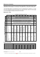
Specifications


TM031 Integrity 18, 20, 24, 26L Service Instructions REV: B
D.O.I: February 2008
This document is stored and maintained electronically by Service. All printed copies not bearing this statement in RED are deemed “uncontrolled”
27
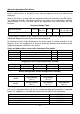
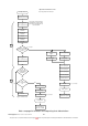
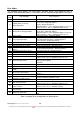
Note: see page 24 for details on interpreting chart abbreviations.
Hot tap closed
Operation Flow Chart
4 & 5
G
.
I
.
S
.
V
(
SVO
)
off
or
[
S
.
V
.
1
-
3
(
SV
1
-
3
)
off
]
Flame current
detected less than
0
.
1
uA
?
YES
YES
Fan
motor speed
checked during
operation
?
YES
NO
YES
Approx
.
6
minutes later
P
.
G
.
F
.
R Valve at
minimum
4
5
Post Purge Shut Down Function
Water flow sensor off
Check gas cut off function by
alternating the closing order of
gas valves SVO and SV
1
-
3
at
each shut down
Fan motor at
minimum
LED off
Fan motor at
minimum
C
.
I
.
Off
S
.
V
.
1
-
3
(
SV
1
-
3
)
failure
80
Flashing
8
seconds later
NO
G
.
I
.
S
.
V
(
SV
0
)
failure
51
Flashing
G
.
I
.
S
.
V
(
SVO
)
off
or
[
S
.
V
.
1
-
3
(
SV
1
-
3
)
off
]
P
.
G
.
F
.
R Valve off
Fan
motor current check
ok
?
Fan off
YES
Abnormal combustion
NO
99
Flashing
Fan off
Isolate power
Locate and repair fault
Use procedure to
clear error code
99
S
.
V
.
1
(
SV
1
)
off
S
.
V
.
2
(
SV
2
)
off
S
.
V
.
3
(
SV
3
)
off
Fan off
G
.
I
.
S
.
V
(
SV
0
)
off
P
.
G
.
F
.
R valve off
Isolate power
Locate and repair fault
and restore power
10
seconds later
10
seconds later