
Specifications


TM031 Integrity 18, 20, 24, 26L Service Instructions REV: B
D.O.I: February 2008
This document is stored and maintained electronically by Service. All printed copies not bearing this statement in RED are deemed “uncontrolled”
35
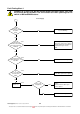
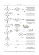
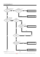
Fault Finding Tests 1 – 4
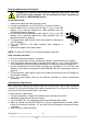
Components will be “Live” when conducting tests, exercise caution.
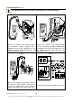
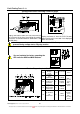
Test 1
Test 2
Measure the voltage at the connector plug to
the transformer primary winding with a
multimeter set on the AC voltage scale. If the
voltage is between 230V and 250V the cord
set and inline fuses are ok.
Measure the voltage at the connector plug
from the transformer secondary winding with
a multimeter set on the AC voltage scale. If
the voltage is between 90V and 110V the
transformer is ok.
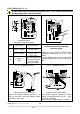
Test 3
Test 4
Measure the voltage at connector A between
R1 and R2 on the PCB with a multimeter set
on the AC voltage scale. If the voltage is
between 90V and 110V the power filter is ok.
Using an insulated tool, turn DIP switch 1 on