
Specifications


TM031 Integrity 18, 20, 24, 26L Service Instructions REV: B
D.O.I: February 2008
This document is stored and maintained electronically by Service. All printed copies not bearing this statement in RED are deemed “uncontrolled”
39
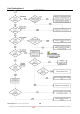
Fault Finding Tests 9 – 13
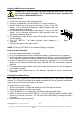
Isolate power when conducting resistance tests. “Live” components present
during voltage tests, exercise caution
Tests 9 and 10 – Diagnostic Point 4
Test 11
Diagnostic Point 4
Conduct test with water flowing
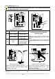
Test
Check Point
Measured Value
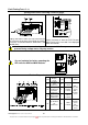
Isolate power before removing
connector plugs
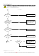
Unplug connector J from the PCB and select
maintenance information 0y on the L.E.D
display.
If 01-07 is displayed the PCB has failed. If 00
is displayed there may be current leakage to
earth
9
4 Blue – 6 White
DC120 -160V
3 Red – 4 Blue
DC11 -19V
10
1 Yellow – 4
Blue
DC4 –10V
(or measurement by
pulse counter of not
less than 4800
pulses per minute)
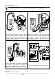
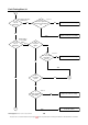
Test 12 - Diagnostic Point 9
Test 13 - Diagnostic Point 12
Conduct test with no water flow
Measure the voltage between terminals 1, 2
and 3 on connector J and earth. Voltage should
be between AC2 – 20V
Conduct test with water flowing
When ignition sequence commences, normal
voltage should be between AC 85 - 110V
until flame is detected.
(Note: Duration is approximately 3 seconds)