
Specifications


TM031 Integrity 18, 20, 24, 26L Service Instructions REV: B
D.O.I: February 2008
This document is stored and maintained electronically by Service. All printed copies not bearing this statement in RED are deemed “uncontrolled”
41
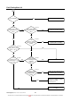
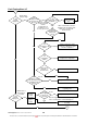
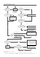
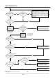
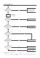
Fault Finding Chart 3.2
YES
Is gas available?
Test 14
NO
Open the gas isolation valve.NO
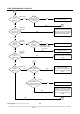
Replace the PCB assembly.NO
Replace the proportional gas flow
regulating valve assembly.
NO
Replace the PCB assembly.NO
Test 18
YES
NO
Set burner pressure correctly.
Replace the combustion chamber
front panel assembly.
Clean the burner.
YES
Test 17
3.2
Replace the proportional gas flow
regulating valve assembly.
Is the
gas pressure correct
at the burner test
point?
YES
Is
there voltage at the
gas inlet solenoid
valve?
NO
Is the
resistance of the gas
inlet solenoid valve
normal?
YES
Test 15
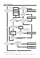
Is there
voltage at solenoid
valves 1, 2 & 3?
YES
Is there
voltage at the
proportional gas flow
regulating
valve?
Is the
resistance of the
solenoid valves 1, 2 &
3 normal?
YES
YES
Test 19 Test 16
Is the
resistance of the
proportional gas flow
regulating valve
normal?
Replace the burner change over
assembly.
NO