
Specifications


TM031 Integrity 18, 20, 24, 26L Service Instructions REV: B
D.O.I: February 2008
This document is stored and maintained electronically by Service. All printed copies not bearing this statement in RED are deemed “uncontrolled”
52
Adjustment
Adjustment of the burner pressure will not overcome problems associated
with poor supply pressure or incorrect gas supply pipe sizing.
Minimum Burner Gas Pressure
1. Remove the front panel from the water heater.
2. Remove burner test point screw and fit manometer.
3. Turn on the remote controller (If fitted).
4. Open a hot tap slowly, to achieve the minimum flow rate at which the burners will ignite.
5. Press and hold the adjuster button (“LH” is displayed on the LED)
NOTE: The adjuster button must be held down continuously through steps 5 and 6.
6. Press the MIN button and observe the reading on the manometer.
NOTE: While the MIN button is pressed, the gas pressure will at first increase then
decrease, cycling between an upper gas pressure limit (39 on LED display) and a lower
gas pressure limit (01 on LED display).
7. Release the MIN and adjuster buttons when the minimum test point pressure shown on
the manometer agrees with the rating label.
NOTE: If the burners extinguish or an error code starts to flash on the LED display during
this procedure, release the MIN and adjuster buttons close the hot tap, clear the error
code, turn on the water heater and recommence the procedure from step 3. To reset an
error code, follow the procedure on page 32.
Maximum Burner Gas Pressure
8. Open the hot tap fully to achieve maximum flow rate.
9. Press and hold the adjuster button (“LH” is displayed on the LED).
NOTE: The adjuster button must be held down continuously through steps 10 and 11.
10. Press the MAX button and observe the reading on the manometer.
NOTE: While the MAX button is pressed, the gas pressure will at first increase then
decrease, cycling between an upper gas pressure limit (39 on LED display) and a lower
gas pressure limit (01 on LED display).
11. Release the MAX and adjuster buttons when the maximum test point pressure shown
on the manometer agrees with the rating label.
12. Turn the hot tap off, remove manometer and refit the burner test point screw ensuring
the seal is gas tight.
13. Refit the front panel to the water heater.
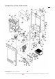
Component Replacement Procedures
Front Panel Removal: (Procedure 1)
1. Isolate power, gas and water supplies.
2. Remove four screws, two from the top and two from the bottom of the front panel.
3. Remove the front panel.