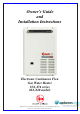
Owner’s Guide and Installation Instructions Electronic Continuous Flow Gas Water Heater 874, 876 series 018, 020 models This water heater must be installed and serviced by an authorised person. Please leave this guide with the householder.
Notice to Victorian Customers from the Victorian Plumbing Industry Commission. This water heater must be installed by a licensed person as required by the Victorian Building Act 1993. Only a licensed person will give you a Compliance Certificate, showing that the work complies with all the relevant Standards. Only a licensed person will have insurance protecting their workmanship for 6 years. Make sure you use a licensed person to install this water heater and ask for your Compliance Certificate.
CONTENTS HOUSEHOLDER - We recommend you read pages 4 to 41. The other pages are intended for the installer but may be of interest. About Your Water Heater ............................................................................................................ 4 Temperature Control ................................................................................................................... 9 Temperature Control – Standard ...........................................................................
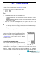
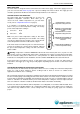
ABOUT YOUR WATER HEATER MODEL TYPE The Rheem® electronic continuous flow gas water heater model you have chosen is for outdoor installation only. This model has an extended warranty (refer to “Warranty” on page 80). The water heater has a maximum preset outlet temperature setting of: 874 series 60 C 876 series 48 C Notes: The 876 series water heater is marked “THIS APPLIANCE DELIVERS WATER NOT EXCEEDING 50°C IN ACCORDANCE WITH AS 3498” on the front panel.
ABOUT YOUR WATER HEATER MAINS PRESSURE The water heater is designed for direct connection to the mains water supply. If the mains supply pressure in your area exceeds that shown on page 44, a pressure limiting valve must be fitted. The supply pressure should be greater than 140 kPa for the rated flow and performance to be achieved.
ABOUT YOUR WATER HEATER WARNING This water heater is only intended to be operated by persons who have the experience or the knowledge and the capabilities to do so. This water heater is not intended to be operated by persons with reduced physical, sensory or mental capabilities i.e. the infirm, or by children. Children should be supervised to ensure they do not interfere with the water heater. The water heater uses 240 Volt AC electrical power for operation of the control systems and the combustion fan.
ABOUT YOUR WATER HEATER TO TURN OFF THE WATER HEATER If it is necessary to turn off the water heater: Turn off the controllers(s) (if fitted) by pressing the on / off button. The light in the on / off button will go out and the priority light (standard controller) or the ACTIVE light (Deluxe controller), if it is on, will go out. Switch off the electrical supply at the power outlet to the water heater if there is no risk of freezing conditions occurring (refer to note below).
ABOUT YOUR WATER HEATER HOW LONG WILL THE WATER HEATER LAST? There are a number of factors that will affect the length of service the water heater will provide. These include the water chemistry, the water pressure, temperature (inlet and outlet) and the water usage pattern. However, your water heater is supported by a comprehensive warranty (refer to page 80). GENERAL MAINTENANCE The jacket of the water heater can be cleaned with a soft cloth and warm mild soapy water.
TEMPERATURE CONTROL CONTROLLERS The Rheem 874 and 876 series can be installed with Rheem controllers to enable the user to control the temperature of the delivered water from the outlet of the water heater. There are two families of Rheem controllers suitable for installation with this water heater. These are the standard controllers and the Deluxe controllers. Standard Controllers There are three types of standard controller.
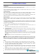
TEMPERATURE CONTROL – STANDARD STANDARD CONTROLLER FUNCTIONS If one or more controllers are installed, at least one must be on for the water heater to operate. If all controllers are off, the water heater will only deliver cold water. on / off button – This button must be pressed once to turn on the controller. A controller cannot be turned on if water is flowing from a hot tap. To turn off a controller, press the on / off button once. The light will go out.
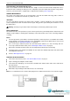
TEMPERATURE CONTROL – STANDARD STANDARD CONTROLLER priority light integrity in use light up button display panel water volume symbol down button water volume operating light on / off operating light water volume button on / off button controller type K = Kitchen B1 = Bathroom1 B2 = Bathroom2 Note: water volume button, water volume operating light and water volume symbol are on the Kitchen controller only.
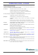
TEMPERATURE CONTROL – STANDARD TEMPERATURE SETTINGS – STANDARD CONTROLLER The temperature settings of each type of controller are: Bathroom1 & 2 37 C to 46 C (in 1 C increments), 48 C*, 50 C Kitchen 37 C to 46 C (in 1 C increments), 48 C*, 50 C, 55 C, 60 C * limited to 48 C on an 876 series model. Temperature settings 37 38 warm 39 40 41 42 43 44 average hot shower 45 46 48 hot 50 55 60 very hot The installation of a Bathroom controller(s) only (i.e.
TEMPERATURE CONTROL – STANDARD TEMPERATURE ADJUSTMENT – STANDARD CONTROLLER A controller must be on and have priority to be able to adjust the temperature setting. The temperature adjustment is made by pressing the up () button or down () button. The maximum temperature setting for the controllers are: Kitchen Bathroom 874 series 60°C 50°C 876 series 48 C 48 C Each press of the up () button will increase the temperature setting by one increment.
TEMPERATURE CONTROL – STANDARD KITCHEN CONTROLLER – STANDARD The Kitchen controller allows the user to select the temperature setting for the hot water to be used in the kitchen and laundry. It has a minimum temperature setting of 37 C and a maximum temperature setting of: 874 series 60ºC 876 series 48 C The Kitchen controller does not have priority if a Bathroom controller is on. Notes on the Kitchen controller: The controller cannot be turned on whilst a hot tap is open.
TEMPERATURE CONTROL – STANDARD To operate the Kitchen controller: 1. Turn off the Bathroom controller(s) 2. If a temperature setting is displayed and the priority light is not glowing, it is necessary to turn off the Bathroom controller(s) to gain priority. Refer to the notes on the Kitchen controller on page 14. Turn on the Kitchen controller pri ori ty i n us e Press the on / off button. 50 The on / off operating light and the priority light will both glow.
TEMPERATURE CONTROL – STANDARD BATHROOM CONTROLLERS – STANDARD The Bathroom controller(s) allows the user to select the temperature setting for the hot water to be used in the bathroom. They have a minimum temperature setting of 37 C and a maximum temperature setting of: 874 series 50ºC 876 series 48 C The Bathroom controllers operate in tandem. Whenever an operation is selected on one Bathroom controller, it is also set on the other Bathroom controller.
TEMPERATURE CONTROL – STANDARD To operate a Bathroom controller: 1. Turn off the Kitchen controller If a temperature setting is displayed and the priority light is not glowing, it is advised to turn off the Kitchen controller. Refer to the notes on the Bathroom controllers on page 16. pri ori ty i n us e 2. Turn on the Bathroom controller 40 Press the on / off button. C The on / off operating light and the priority light will both glow. The temperature setting of 40 C will be displayed. 3.
TEMPERATURE CONTROL – STANDARD WATER VOLUME FUNCTION – STANDARD CONTROLLER The water volume function is designed to warn, by a beeping sound, that a certain volume of water has been delivered from the water heater. It does not stop either the flow of or the heating of water. This function is particularly useful if a bath is being filled, or measuring the water consumed by the use of a shower. The water volume function can only be set by the Kitchen controller.
TEMPERATURE CONTROL – STANDARD 5. Turn off the alarm pri ori ty i n us e Press the water volume button to turn off the alarm. 42 The water volume operating light goes out and 0 x10l is displayed momentarily on the controller. C x10l The temperature setting of the controller with priority is then displayed. check hot water temperature before use 6.
TEMPERATURE CONTROL – DELUXE DELUXE CONTROLLER FUNCTIONS If one or more Deluxe controllers are installed, at least one must be on or the bath fill function activated for the water heater to operate. If all Deluxe controllers and the bath fill function are off, the water heater will only deliver cold water. ON / OFF button – The ON / OFF button must be pressed once to turn on the Deluxe controller. A Deluxe controller cannot be turned on if water is flowing from a hot tap.
TEMPERATURE CONTROL – DELUXE bath fill water volume display panel – The selected bath fill water volume is displayed in litres on all Deluxe controllers. The selected bath fill water volume is displayed whenever the Bath Fill mode is on (refer to “Bath Fill Mode” on page 30) or when the bath fill water volume is being adjusted and the Bath Fill mode is off.
TEMPERATURE CONTROL – DELUXE VOICE PROMPT AND OPERATING TONE The Deluxe controllers have a series of voice prompts and operating tones which sound during certain operations. The voice prompts and operating tones sound from all Deluxe controllers, regardless of which Deluxe controller is being operated at the time.
TEMPERATURE CONTROL – DELUXE Adjusting the Volume of the Voice Prompt and Operating Tone The volume of the voice prompt and the operating tone can be adjusted to a level comfortable for you. The volume of the voice prompt and the operating tone can be adjusted independently of each other. The volume levels on a Deluxe controller are adjusted independently of another Deluxe controller.
TEMPERATURE CONTROL – DELUXE TEMPERATURE SETTINGS – DELUXE CONTROLLERS The temperature settings of each type of Deluxe controller are: Bathroom1 & 2 Deluxe 37 C to 46°C (in 1 C increments), 48 C*, 50 C Kitchen Deluxe 37 C to 46°C (in 1 C increments), 48 C*, 50 C, 55 C, 60 C * limited to 48 C on an 876 series model and when set to Bath Fill mode on 874 series model. This is to ensure the water temperature does not exceed 50°C.
TEMPERATURE CONTROL – DELUXE TEMPERATURE ADJUSTMENT – DELUXE CONTROLLERS A controller must be on with the ACTIVE indicator displayed to be able to adjust the temperature setting. The temperature adjustment is made by pressing the up () button or down () button. The minimum temperature setting for each type of controller is 37 C.
TEMPERATURE CONTROL – DELUXE KITCHEN CONTROLLER – DELUXE The Kitchen Deluxe controller allows the user to select the temperature setting for the hot water to be used in the kitchen and laundry. It has a minimum temperature setting of 37 C and a maximum temperature setting of: 874 series 60ºC 876 series 48 C The Kitchen Deluxe controller does not have priority (ACTIVE light is off) if a Bathroom Deluxe controller is on.
TEMPERATURE CONTROL – DELUXE To operate the Kitchen Deluxe controller: 1. Turn off the Bathroom Deluxe controller(s) 2. If a temperature setting is displayed and the ACTIVE light is not glowing, it is necessary to turn off the Bathroom Deluxe controller(s) to gain priority. Refer to the notes on the Kitchen Deluxe controller on page 26. 8888 BATH (l) °C ON/OFF Rheem Press the ON / OFF button. The light in the ON / OFF button and the ACTIVE light will both glow.
TEMPERATURE CONTROL – DELUXE BATHROOM CONTROLLERS – DELUXE The Bathroom Deluxe controller(s) allows the user to select the temperature setting for the hot water to be used in the bathroom. They have a minimum temperature setting of 37 C and a maximum temperature setting of: 874 series 50ºC 876 series 48 C The Bathroom Deluxe controllers operate in tandem. Whenever an operation is selected on one Bathroom Deluxe controller, it is also set on the other Bathroom Deluxe controller.
TEMPERATURE CONTROL – DELUXE To operate a Bathroom Deluxe controller: 1. Turn off the Kitchen Deluxe controller If a temperature setting is displayed and the ACTIVE and ON / OFF operating lights are not glowing, it is advised to turn off the Kitchen Deluxe controller. Refer to the notes on the Bathroom Deluxe controllers on page 28. 2. 8888 BATH (l) °C ON/OFF Rheem Press the ON / OFF button. The light in the ON / OFF button and the ACTIVE light will both glow.
TEMPERATURE CONTROL – DELUXE BATH FILL MODE The Bath Fill mode is designed to allow the water heater to deliver a selected volume of water at a selected temperature. The Bath Fill mode commences when the BATH FILL button is on and a hot tap is opened. When the set volume has been delivered, the water flow from the water heater ceases and heating stops. It is also useful for controlling the water volume used by a shower or other application.
120 40 BATH (l) TEMPERATUREBATH CONTROL – DELUXE FILL ON/OFF 5. Close the front panel on the Deluxe controller. 6. Turn on the Bath Fill mode Rheem Press the BATH FILL button. On all Deluxe controllers: The BATH FILL operating light will glow. The bath fill temperature setting will appear on the temperature display panel. The bath fill water volume will appear on the bath fill water volume display panel. 7. ACTIVE The bath fill indicator light will glow.
TEMPERATURE CONTROL – DELUXE Bath Fill Mode – Explanatory Notes To operate the Bath Fill mode: 1. Turn off all Deluxe controllers It is advised to turn off all Deluxe controller(s) before activating the Bath Fill mode. ACTIVE 120 Refer to the notes on the Bathroom Deluxe controllers on page 28. BATH (l) The Deluxe controllers do not need to be on to set the bath fill temperature and bath fill water volume and to turn on the Bath Fill mode. BATH FILL ON/OFF BATH FILL VOLUME 2.
TEMPERATURE CONTROL – DELUXE 4. Set the bath fill water volume Press the BATH FILL VOLUME (up button) or the BATH FILL VOLUME (down button). ACTIVE The first press of either the BATH FILL VOLUME (up button) or the BATH FILL VOLUME (down button) will display the last selected bath fill water volume setting in the bath fill water volume display panel and the bath fill indicator light will glow.
TEMPERATURE CONTROL – DELUXE 7. Open the hot tap. The operating light will glow on all Deluxe controllers. Measurement of the water flow at the water heater will commence when the hot tap is opened. ACTIVE 120 BATH (l) 40 °C Notes: If a second hot tap is opened when the Bath Fill mode is turned on, the set bath fill water volume expected from the first hot tap will be reduced by the volume which flows through the second hot tap.
TEMPERATURE CONTROL – DELUXE Turning Off Bath Fill Mode During Its Operation The bath fill operation can be interrupted by pressing the BATH FILL button before completion of the bath fill operation.
TEMPERATURE CONTROL – DELUXE Notes on the Bath Fill mode: The Bath Fill mode can be set, turned on and turned off at any of the Deluxe controllers. The Deluxe controllers do not require to have priority (ACTIVE light glowing) or be on in order to set the bath fill water volume or bath fill temperature or to turn the BATH FILL button on. The BATH FILL button cannot be turned on whilst a hot tap is open.
TEMPERATURE CONTROL – DELUXE Opening a Second Hot Water Tap During Bath Fill Operation The bath fill water volume is measured as the water flows through the water heater. If more than one hot tap is open, the Bath Fill mode will measure the total water volume drawn from all taps and the expected water volume from the first tap will be decreased.
TEMPERATURE CONTROL – DELUXE Operation of the Bath Fill mode whilst a Deluxe Controller is ACTIVE It is recommended the Bath Fill mode be set and operated with the Deluxe controllers turned off (refer to Step 1 on page 32).
SAVE A SERVICE CALL Check the items below before making a service call. You will be charged for attending to any condition or fault, which is not related to manufacture or failure of a part (refer to “Warranty” on page 80). NO DISPLAY ON THE CONTROLLER Is the controller turned on? Press the on / off button (refer to “Temperature Control” on pages 9 to 38). Is the water heater plugged in and the power outlet switched on? Is power available in the house? Try using another electrical appliance.
SAVE A SERVICE CALL GAS BOOSTER OPERATING TOO FREQUENTLY If the water heater is installed as a gas booster water heater to a solar preheat water heater, you may find that the water heater operates more frequently than expected. This will occur when the solar preheat water temperature is lower than 58°C, which may be experienced during periods of low solar energy gain or if there has been heavy hot water usage.
SAVE A SERVICE CALL CLOUDS OF WHITE ‘VAPOUR’ FROM THE FLUE TERMINAL During the heating cycle, it is not unusual to see water vapour clouds steaming from the flue terminal, particularly on cold days. This is normal operation of the water heater. PRESSURE RELIEF VALVE DISCHARGING A pressure relief valve is incorporated into the water heater controls. This valve protects the water heater, by allowing water to escape, in the event of excessive pressure build up in the waterways.
INSTALLATION – WATER HEATER THIS WATER HEATER IS FOR OUTDOOR INSTALLATION ONLY. THIS WATER HEATER IS NOT SUITABLE FOR POOL HEATING. Check the water heater is suitable for the gas type available. (refer to the rating label on the water heater) The 874 series of water heater may be installed as an in-series gas booster water heater to a solar preheat water heater.
INSTALLATION – WATER HEATER As a guide the following requirements extracted from the Australian Gas Installations Standard AS 5601, must be observed. At least 300 mm between the top of the flue terminal and the eaves. At least 300 mm between the flue terminal and the edge of any opening into the building, measured horizontally along the wall. At least 300 mm between the flue terminal and a return wall or external corner, measured horizontally along the wall.
INSTALLATION – WATER HEATER MAINS WATER SUPPLY Where the mains water supply pressure exceeds that shown in the table below, an approved pressure limiting valve that does not have non return valve characteristics (such as an RMC PSL series valve) is required and should be fitted as shown in the installation diagram (refer to page 52). Model 018 - 020 Relief valve setting 1750 kPa Max. mains supply pressure 1000 kPa Min.
INSTALLATION – WATER HEATER HOT WATER DELIVERY This water heater can deliver water at temperatures which can cause scalding. It is necessary and we recommend that a temperature limiting device be fitted between an 874 series water heater and the hot water outlets in any ablution and public areas such as a bathroom, ensuite or public amenities, to reduce the risk of scalding.
INSTALLATION – WATER HEATER Where a temperature limiting device is installed adjacent to the gas booster water heater, the cold water line to the temperature limiting device can be branched off the cold water line either before or after the isolation valve and pressure limiting valve to the solar storage tank, but it MUST BE before the non return valve prior to an open circuit direct system.
INSTALLATION – WATER HEATER CIRCULATED HOT WATER FLOW AND RETURN SYSTEM A Rheem continuous flow water heater cannot be installed as part of a circulated hot water flow and return system in a building. If a circulated flow and return system is required, it is necessary to bypass the continuous flow water heater and install a secondary water heater connected to the hot water flow and return line and supplied from the continuous flow water heater.
INSTALLATION – WATER HEATER WATER TEMPERATURE DIAGRAMS 874 Series - Kitchen and Bathroom Controllers 876 Series – Kitchen and Bathroom Controllers 874 Series - Kitchen Controller Only 876 Series - Kitchen Controller Only 874 Series - Bathroom Controllers Only 876 Series - Bathroom Controllers Only 874 Series - No Controllers 876 Series - No Controllers Notes: Temperature Limiting Devices – refer to “Hot Water Delivery” on page 45.
INSTALLATION – WATER HEATER DIMENSIONS AND TECHNICAL DATA Model 874 018 876 018 874 020 876 020 Rated delivery (@ 40 C rise) litres / min 11.3 12.5 Recovery (@ 25 C rise) litres / min 18 20 kg 18 18 Mass Empty Gas Details Natural Propane Hourly Gas Consumption (MJ) Min. Gas Pressure (kPa) Test Point Gas Pressure (kPa) minimum maximum Max. Gas Pressure (kPa) 018 020 018 to 020 018 020 018 020 018 to 020 140 140 153 153 1.13 2.75 0.170 0.190 0.170 0.190 0.740 0.885 0.
INSTALLATION – WATER HEATER DIMENSIONS – STANDARD CONTROLLERS Kitchen Controller (Standard) Bathroom Controller (Standard) 50
INSTALLATION – WATER HEATER DIMENSIONS – DELUXE CONTROLLERS 120 24 120 24 120 120 120 120 Deluxe Controller – Cover Closed Bath Fill Bath Water Volume 1. U P U U P U 2. 3. Bath Fill Temp Bath Fill Set Bath 1. Fill Water 2. Volume and Temperature Bath Hot Water Water Volume Bath Fill Temp 1. Set Bath Fill Water Volume and Temperature ON/OFF Hot Water 5. 120 120 120 120 160 160 160 160 7.
TYPICAL INSTALLATION INSTALLATION – WATER HEATER ELECTRONIC INSTANTANEOUS GAS WATER HEATER TYPICAL INSTALLATION – OUTDOOR LOCATION 52
INSTALLATION – WATER HEATER TYPICAL INSTALLATION – GAS BOOSTER FOR SOLAR WATER HEATER Typical Installation Solar In-Line GasWater Booster Solar Loline Open Circuit With-An In-Series Gas Booster Heater Solar Pumped Open Circuit Systems Typical Installation Solar Premier Loline Closed Circuit With An In-Series Gas Booster Water Heater Solar Drain Back Storage Tank with Remote In-Series Gas Boost 53
INSTALLATION – WATER HEATER Solar Hiline Open Circuit With An In-Series Gas Booster Water Heater TYPICAL INSTALLATION SOLAR OPEN CIRCUIT THERMOSIPHON WITH IN-SERIES GAS BOOSTER TYPICAL Solar Premier Hiline Closed Circuit INSTALLATION With An In-Series Gas Booster Water Heater SOLAR CLOSED CIRCUIT THERMOSIPHON WITH IN-SERIES GAS 54 BOOSTER
CONNECTIONS – PLUMBING CONNECTION SIZES Model 018 to 020 Hot water connection R¾/20 Cold water connection R¾/20 Gas inlet R¾/20 All plumbing work must be carried out by a qualified person and in accordance with the National Plumbing Standard AS/NZS 3500.4 and local authority requirements. All gas work must be carried out by a qualified person and in accordance with the Australian Gas Installations Standard AS 5601 and local authority requirements.
CONNECTIONS – PLUMBING PIPE SIZES The pipe sizing for hot water supply systems should be carried out by persons competent to do so, choosing the most suitable pipe size to ensure adequate flow for each individual application. Reference to the technical specifications of the water heater and local regulatory authority requirements must be made. To achieve true mains pressure operation, the cold water line to the water heater should be the same size or bigger than the hot water line from the water heater.
CONNECTIONS – ELECTRICAL All electrical work and permanent wiring must be carried out by a qualified person and in accordance with the Wiring Rules AS/NZS 3000 and local authority requirements. Warning: Temperature controllers must not be fitted to this water heater (874 series) as part of a solar water heater system or if a Water Star water heater is installed because water at a temperature much higher than the controller setting can be delivered.
EZ-LINK SYSTEM DUAL INSTALLATION The EZ-Link™ system is designed to electronically control two continuous flow gas water heaters and have them operate as one. One or both water heaters may be in operation, depending upon the hot water demand. The second water heater will only operate when the hot water demand exceeds the capacity of the first water heater to supply. The EZ-Link system is suitable for installation with Rheem 874 and 876 series 018 and 020 models continuous flow gas water heaters.
EZ-LINK SYSTEM DUAL INSTALLATION DUAL INSTALLATION Install two continuous flow water heaters of the same model in an Equa-Flow® manifold plumbing arrangement. The two continuous flow water heaters can be installed side by side with minimal clearance between them. The AGA has approved the installation of two Rheem 874 and 876 series 018 and 020 model water heaters with an exemption from the 300 mm minimum clearance requirements between flue terminals, as stated in AS 5601, clause 5.13.6.5.
EZ-LINK SYSTEM DUAL INSTALLATION EZ-LINK CABLE CONNECTION The references in steps 5 to 8 are to the „Control Board with Ez-Link Connection‟ diagram on page 61. To connect the Ez-Link cable to the water heaters: 1. Close any hot taps and ensure the burners on both water heaters are not operating. 2. Switch off the electrical supply at the power outlet to each water heater. 3. Remove the screws holding the front panel to the jacket on each water heater. 4.
EZ-LINK SYSTEM DUAL INSTALLATION Controller Cable (one water heater only) SW2 1 2 3 4 1 2 3 4 E REMOTE CONTROLLER TERMINAL ON ON OFF DIP1 SW1 ON Ez-Link Cable 1 2 3 4 OFF DIP1 ON Secure cable with cable clamp & screw E 1 2 3 4 Dip Switch 4 in the on (up) position MANIFOLD INSTALLATION - EZ Connection LINK CONNECTION Control Board with Ez-Link TWO CONTINUOUS FLOW WATER HEATERS eaves, balconies & other projections no minimum Ez-Link Cable Connection distance 350 requirement 300 MI
INSTALLATION – CONTROLLERS CONTROLLERS The Rheem 874 and 876 series can be installed with Rheem controllers to enable the user to control the temperature of the delivered water from the outlet of the water heater. There are two families of Rheem controllers suitable for installation with this water heater. These are the standard controllers and the Deluxe controllers. Standard Controllers There are three types of standard controller.
INSTALLATION – CONTROLLERS KITCHEN CONTROLLER The standard Kitchen controller (Rheem PN 299853) or Kitchen Deluxe controller (Rheem PN 299861) is to be installed in the kitchen or laundry only. It has a minimum temperature setting of 37 C and a maximum temperature setting of: 874 series 60°C 876 series 48 C Choose a suitable location for the Kitchen controller, away from water, heat and sunlight.
INSTALLATION – CONTROLLERS Wiring installation: 1. Penetrate the wall with a 30-35 mm hole at the controller location. 2. Install the Kitchen controller cable between the location of the controller and the water heater. 3. Remove the base plate from the controller. 4. Draw the cable through the central hole in the base plate. 5. Fix the base plate to the wall using suitable screws and wall anchors. Ensure the projections in the base plate are pointing upwards. 6.
INSTALLATION – CONTROLLERS If it is necessary to have an exposed wiring installation, follow this procedure omitting Steps 1 and 4, and make an opening in the thin section in the underside of the controller to accommodate the cable (as shown in the diagram), prior to Step 6.
INSTALLATION – CONTROLLERS BATHROOM1 AND BATHROOM2 CONTROLLERS If only one Bathroom controller is to be installed, the standard Bathroom1 Controller (Rheem PN 299854) or the Bathroom1 Deluxe controller (Rheem PN 299862) must be used.
INSTALLATION – CONTROLLERS Wiring installation: 1. Penetrate the wall with a 30-35 mm hole at the controller location. 2. Install the supplied cable between the location of the controller and the water heater. 3. Remove the base plate from the controller. 4. Peel off one side of the adhesive paper from the foam packing and adhere to the back face of the base plate. This is the side without the projections. 5. Peel off the remaining adhesive paper from the foam packing. 6.
INSTALLATION – CONTROLLERS CONNECTING THE CONTROLLER(S) TO THE WATER HEATER To connect the controller(s) to the water heater: 1. Ensure the electrical supply to the water heater is switched off. 2. Unscrew and gently remove the front panel from the water heater. 3. Draw the cable(s) through the cable grommet on the underside of the water heater. 4. Connect a cable lug from each cable to each of the remote controller terminals. Each cable has two cable lugs.
COMMISSIONING All water heaters are tested and adjusted before dispatch from the factory, however further adjustments may become necessary because of local conditions. TO TURN ON THE WATER HEATER Open all of the hot taps in the house (don‟t forget the shower). Open the cold water isolation valve fully at the inlet to the water heater. Air will be forced out of the taps. Close each tap as water flows freely from it. Check the pipe work for leaks. Open the gas isolation valve fully.
COMMISSIONING Gas Inlet Test Point Pressure To check the gas inlet pressure: 1. Close any hot taps and ensure the burners are not operating. 2. Close the gas isolation valve at the gas inlet to the water heater. 3. Locate the gas inlet test point on the gas connection to the water heater. 4. 5. Remove the test point screw and washer from the test point orifice. Connect the manometer. WASHER Open the gas isolation valve fully at the gas inlet to the water heater.
COMMISSIONING BURNER GAS PRESSURE It is necessary to check the burner gas pressure at both the minimum and maximum operational settings. To check and if necessary adjust the operational gas pressures, the electrical supply to the water heater must be switched on, the burners ignited and hot water must be flowing from a hot tap. Warning: The removal of the front panel will expose 240 volt wiring. Take care not to touch wiring terminals.
COMMISSIONING 11. Press and hold down the MIN button (“1L” is shown on the controller display), and observe the reading on the manometer. The red LED will glow and remain solid. 12. Release the MIN button. The red LED goes out. If the manometer reading observed in step 11 agrees with the rating label, no further adjustment is required. 13. To adjust, press and hold down the adjuster button (“LH” is shown on the controller display). The red LED will glow and remain solid.
COMMISSIONING Maximum test point gas pressure Refer to the rating label on the water heater for the maximum test point gas pressure. Follow Steps 10 to 16 of the “Minimum test point gas pressure” procedure, but open the hot tap fully and use the MAX button instead of the MIN button. It may be necessary to open two or three hot taps fully, depending upon the model of water heater and the incoming cold water temperature. Note: In Step 11, “3H” (018, 020 models) will be shown on the controller display.
COMMISSIONING PRESET OUTLET TEMPERATURE SETTING The factory preset outlet temperature setting of the water heater is: 874 series 60°C 876 series 48°C If a temperature controller is connected to the water heater, this will override the preset outlet temperature setting and the maximum temperature setting will be: Maximum Outlet Temperature 874 series 876 series Kitchen controller connected 60°C 48°C Bathroom controller only connected 50°C 48°C It is usually not necessary to check or adjust the
COMMISSIONING It is necessary to have the electrical supply to the water heater switched on during stages of checking or adjusting the preset outlet temperature setting procedure. Warning: The removal of the front panel will expose 240 volt wiring. Take care not to touch wiring terminals. The adjustment must be carried out by a qualified person. Warning: This procedure will involve the adjustment of dip switches. Adjustment of a dip switch should only be made with an insulated tool.
COMMISSIONING TO TURN OFF THE WATER HEATER If it is necessary to turn off the water heater on completion of the installation, such as on a building site or where the premises is vacant, then: Turn off the controllers(s) (if fitted) by pressing the on / off button. The light in the on / off button will go out and the priority light (standard controller) or the ACTIVE light (Deluxe controller), if it is on, will go out.
DRAINING THE WATER HEATER To drain the water heater: Turn off the water heater (refer to “Turn Off The Water Heater” on page 76). Open a hot tap (preferably the shower outlet). Unscrew the two drain plugs, one each at the cold water inlet and hot water outlet, on the underside of the water heater. Water will drain from the water heater. When water stops flowing from the water heater, close the hot tap.
This page is intentionally blank.
RHEEM ELECTRONIC CONTINUOUS FLOW GAS WATER HEATER WARRANTY – AUSTRALIA ONLY WARRANTY CONDITIONS 1. This warranty is applicable only to water heaters manufactured from 1st April 2008. 2. The water heater must be installed in accordance with the Rheem water heater installation instructions, supplied with the water heater, and in accordance with all relevant statutory and local requirements of the State in which the water heater is installed. 3.
RHEEM ELECTRONIC CONTINUOUS FLOW GAS WATER HEATER WARRANTY – AUSTRALIA ONLY WARRANTY Rheem* will: a) Repair or, if necessary replace any Rheem water heater; or b) Replace any component (or, if necessary, arrange the installation of a new water heater), which falls within the Warranty Periods specified below, subject to the warranty conditions and exclusions.