Owner’s Guide and Installation Instructions Solar Loline Storage Tank WARNING: Plumber – Be Aware Use copper pipe ONLY. Plastic pipe MUST NOT be used. It is a requirement of a solar water heater installation that all pipe work be in copper and not plastic, due to the effects of high water temperatures and pressures. This water heater must be installed and serviced by a qualified person. Please leave this guide with the householder.
WARNING: Plumber – Be Aware The solar hot and solar cold pipes between the solar storage tank and the solar collectors MUST BE of copper. All compression fittings must use brass or copper olives. The full length of the solar hot and solar cold pipes MUST BE insulated.
CONTENTS HOUSEHOLDER – We recommend you read pages 4 to 19. The other pages are intended for the installer but may be of interest. About Your Water Heater ............................................................................................................ 4 Regular Care .............................................................................................................................. 11 Water Supplies.......................................................................................
ABOUT YOUR WATER HEATER WATER HEATER APPLICATION This water heater is designed for use in a single family domestic dwelling for the purpose of heating potable water. Its use in an application other than this may shorten its life. MODEL TYPE ® ® Your Rheem Loline 511 220 water heater is designed for the solar collectors to be roof mounted and the vitreous enamel lined solar storage tank to be installed at ground or floor level, remotely from the solar collectors.
ABOUT YOUR WATER HEATER MAINS PRESSURE The water heater is designed to operate at mains pressure by connecting directly to the mains water supply. If the mains supply pressure in your area exceeds that shown on page 23, a pressure limiting valve must be fitted. The supply pressure should be greater than 350 kPa for true mains pressure operation to be achieved. A minimum water supply pressure of 200 kPa is required to enable the solar circulator and solar circuit system to operate effectively.
ABOUT YOUR WATER HEATER SAFETY This water heater is supplied with a thermostat, an over temperature energy cut-out, temperature sensors and a combination temperature pressure relief valve. These devices must not be tampered with or removed. The water heater must not be operated unless each of these devices is fitted and is in working order. The operation of the over-temperature cut-out on the thermostat indicates a possibly dangerous situation.
ABOUT YOUR WATER HEATER FREEZE PROTECTION The system has a level of freeze protection designed to guard the system against damage from freeze conditions. The system must be installed with the full length of the solar hot and solar cold pipes insulated to offer protection against freeze damage (refer to “Pipe Work and Insulation” on page 6). Freeze conditions occur below 6°C.
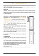
ABOUT YOUR WATER HEATER SOLAR MONITOR A solar monitor is located on the front of the top cover and houses both a green and a red LED. The green LED, marked “Solar”, indicates the current operational mode of the solar water heater and the red LED, marked “Attention”, indicates a fault mode. The green LED will emit either a constant glow or a series of flashes, with a 2 second interval between each series.
ABOUT YOUR WATER HEATER BLEEDING THE SOLAR COLLECTORS It is necessary to purge air from the collector circuit: When the water heater is to be turned on and the solar collectors and solar hot and solar cold pipes have been drained. After maintenance has been conducted on the pipe work and air has entered the system. If the circulator appears not to be circulating water around the system.
ABOUT YOUR WATER HEATER TO TURN ON THE WATER HEATER Open the cold water isolation valve fully at the inlet to the water heater. If the solar collectors and solar hot and solar cold pipes have been drained, it will be necessary to bleed the collector circuit (refer to “Bleeding the Solar Collectors” on page 9). If the electrical supply to the water heater has been switched off: Switch on the electrical supply at the power outlet to the solar storage tank.
REGULAR CARE MINOR SIX MONTH MAINTENANCE It is recommended minor maintenance be performed every six months by the dwelling occupant. The minor maintenance includes: Operate the easing lever on the temperature pressure relief valve. It is very important you raise and lower the lever gently. Refer to “Temperature Pressure Relief Valve” on page 12. Warning: Exercise care to avoid any splashing of water, as water discharged from the drain line will be hot.
REGULAR CARE TEMPERATURE PRESSURE RELIEF VALVE This valve is near the top of the water heater and is essential for its safe operation. It is possible for the valve to release a little water through the drain line during each heating period. This occurs as the water is heated and expands by approximately 1/50 of its volume. Continuous leakage of water from the valve and its drain line may indicate a problem with the water heater (refer to “Temperature Pressure Relief Valve Running” on page 18).
REGULAR CARE FLUSHING THE SOLAR COLLECTORS It may be necessary to flush the solar collectors if there is sediment in the water supply. This should be conducted in the morning, within three hours of sunrise, when the water temperature inside the solar collectors is lower. Open a hot water tap and allow the water to run for five (5) minutes prior to flushing the solar collectors. Close the hot tap. Wait a further five (5) minutes before attempting to flush the solar collectors.
WATER SUPPLIES This water heater must be installed in accordance with this advice to be covered by the Rheem warranty. This water heater is manufactured to suit the water conditions of most public reticulated water supplies. However, there are some known water chemistries which can have detrimental effects on the water heater and its operation and / or life expectancy. If you are unsure of your water chemistry, you may be able to obtain information from your local water supply authority.
WATER SUPPLIES ANODE INSPECTION AND REPLACEMENT The anode installed in a vitreous enamel lined steel water heater cylinder will slowly dissipate whilst protecting the cylinder. The life of the cylinder may be extended by replacing the anode. If the anode is not replaced during a five year service (refer to “Major Five Year Service” on page 11) then the maximum time after installation when the anode should be replaced is 8 years.
WATER SUPPLIES WITHIN WARRANTY SPECIFICATION -1.0 very corrosive 0 +0.4 no warranty applies to a: -standard watts density heating unit -direct (open circuit) solar collector no warranty applies to a: temperature pressure relief valve or a water heater cylinder unless an expansion control valve is fitted. no warranty applies to a: -copper sheathed heating unit -direct (open circuit) solar collector SATURATION INDEX (SI) SOLAR WATER HEATERS WITH ELECTRIC HEATING UNIT +0.
SAVE A SERVICE CALL Check the items below before making a service call. You will be charged for attending to any condition or fault that is not related to manufacture or failure of a part. NOT ENOUGH HOT WATER (OR NO HOT WATER) Insufficient sunlight Insufficient sunlight due to cloudy weather during hotter months or low solar energy contribution in colder months may mean the in-series water heater operates more often.
SAVE A SERVICE CALL TEMPERATURE PRESSURE RELIEF VALVE RUNNING Normal Operation It is normal and desirable this valve allows a small quantity of water to escape during the heating cycle. However, if it discharges more than a bucket full of water in 24 hours, there may be another problem. Continuous dribble Try gently raising the easing lever on the relief valve for a few seconds (refer to “Temperature Pressure Relief Valve” on page 12).
SAVE A SERVICE CALL HIGHER THAN EXPECTED GAS BILLS With the installation of your new solar hot water system, maximum energy savings can be achieved with careful planning of hot water usage. Should you at any time feel your energy account is higher than expected, we suggest you check the following points: Is the relief valve running excessively? Refer to “Temperature Pressure Relief Valve Running” on page 18).
INSTALLATION – SOLAR STORAGE TANK THIS WATER HEATER IS FOR OUTDOOR INSTALLATION ONLY IF AN IN-SERIES GAS BOOSTER IS MOUNTED ON THE STORAGE TANK. THIS WATER HEATER IS NOT SUITABLE FOR POOL HEATING. The system is suitable for installation with one or two HBT 200 solar collectors. The system is not suitable for installation above 400 metres altitude.
INSTALLATION – SOLAR STORAGE TANK INSTALLATION STANDARDS The water heater must be installed: by a qualified person, and in accordance with the installation instructions, and in compliance with Standards AS/NZS 3500.4, AS/NZS 3000 and all local codes and regulatory authority requirements. In New Zealand, the installation must also conform with Clause G12 of the New Zealand Building Code.
INSTALLATION – SOLAR STORAGE TANK Clearance must be allowed for servicing of the solar storage tank. The solar storage tank must be accessible without the use of a ladder or scaffold. Make sure the temperature pressure relief valve lever is accessible and the front cover, thermostat and booster heating unit can be removed for service. You must be able to read the information on the rating plate. If possible leave headroom of one water heater height so the anode can be inspected or replaced.
INSTALLATION – SOLAR STORAGE TANK SAFE TRAY Where damage to property can occur in the event of the water heater leaking, the water heater must be installed in a safe tray. Construction, installation and draining of a safe tray must comply with AS/NZS 3500.4 and all local codes and regulatory authority requirements. AS/NZS 3500.4 also has particular requirements when a safe tray must be installed.
INSTALLATION – SOLAR STORAGE TANK If a combination isolation valve and non return valve (duo or trio valve) is installed on the cold water line to the solar water heater and the cold water line to the temperature limiting device branches off after this valve, then a second non return valve must be installed between the cold water branch and the solar storage tank.
INSTALLATION – SOLAR STORAGE TANK CIRCULATED HOT WATER FLOW AND RETURN SYSTEM The solar storage tank of a solar water heater should not be installed as part of a circulated hot water flow and return system in a building. The benefits of solar gain will be significantly reduced and energy gained from the sun lost through the pipe work.
INSTALLATION – SOLAR STORAGE TANK Integrated In-series Gas Booster as part of a Direct 511 220 Solar Water Heater Installation Circulated Hot Water Flow and Return System LEGEND Remote In-series Gas Booster as part of a Direct 511 220 Solar Water Heater Installation Circulated Hot Water Flow and Return System LEGEND REDUCING HEAT LOSSES The cold water line to and the hot water line from the water heater must be insulated in accordance with the requirements of AS/NZS 3500.4.
INSTALLATION – SOLAR STORAGE TANK ANODE The vitreous enamel lined cylinder of the water heater is only covered by the Rheem warranty when the total dissolved solids (TDS) content in the water is less than 2500 mg/L and when the correct colour coded anode is used. If an incorrect colour coded anode is used in the water heater, any resultant faults will not be covered by the Rheem warranty. In addition, the use of an incorrect colour coded anode may shorten the life of the water heater cylinder.
INSTALLATION – SOLAR STORAGE TANK DIMENSIONS AND TECHNICAL DATA Model Capacity 511 220 220 litres Tank Mass (kg) (without booster) Empty Full 77 297 Tank Mass (kg) (with booster) Empty Full 95 (20L) 315 (20L) 100 (27L) 320 (27L) Technical data is subject to change.
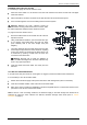
INSTALLATION – SOLAR STORAGE TANK TYPICAL INSTALLATION (INTEGRATED BOOST) – OUTDOOR LOCATION HOT SENSOR CONNECTION SOLAR HOT PIPE Insulated copper pipe. Use a union connection at the bleed valve and non return valve assembly. Use a union connection at collector Nylon olives must NOT be used HOT SENSOR LEAD SOLAR COLD PIPE Insulated copper pipe. Use union connection at tank and collector.
INSTALLATION – SOLAR STORAGE TANK TYPICAL INSTALLATION (REMOTE BOOST) – OUTDOOR LOCATION HOT SENSOR CONNECTION HOT SENSOR CONNECTION SOLAR HOT PIPE Insulated copper pipe. SOLAR HOT PIPE Use a unioncopper connection Insulated pipe. at the bleedconnection valve and Use a union non return at the valve bleed assembly. valve and Use a union collector non connection return valveatassembly.
INSTALLATION – SOLAR COLLECTORS SOLAR COLLECTOR LOCATION Consideration must be given to the position of the solar collectors in relation to the solar storage tank. There are limitations on the maximum length of the solar hot and solar cold pipes between the solar storage tank and the solar collectors. Refer to “Solar Storage Tank Location” on page 21 and to “Pipe Lengths” on page 32. The solar collectors must be installed in a shade free position.
INSTALLATION – SOLAR COLLECTORS LATITUDE OF SOME AUSTRALIAN CITIES Adelaide 35°S Cairns 17°S Hobart 42°S Port Hedland 20°S Alice Springs 24°S Canberra 35°S Mildura 34°S Rockhampton 24°S Brisbane 27°S Darwin 12°S Melbourne 38°S Sydney 34°S Broken Hill 31°S Geraldton 28°S Perth 32°S Townsville 19°S PIPE LENGTHS The solar hot and solar cold pipes between the solar storage tank and the solar collectors shall: be of bendable grade or hard drawn copper tube.
INSTALLATION – SOLAR COLLECTORS WARNING: Plumber – Be Aware The solar hot and solar cold pipes between the solar storage tank and the solar collectors MUST BE of copper. All compression fittings must use brass or copper olives. The full length of the solar hot and solar cold pipes MUST BE insulated.
INSTALLATION – SOLAR COLLECTORS Maximum Height To Collectors The maximum height of a solar Loline installation, from the solar controller (circulator) to the top of the solar collectors, is determined by the maximum recommended total pipe length for the system and the water supply pressure.
INSTALLATION – SOLAR AND GAS BOOSTER CONNECTIONS GROUND KIT A „Ground Kit‟ is supplied with the solar storage tank. The kit contains the components to enable the: connection of the solar cold and solar hot pipes to the solar storage tank mounting of an in-series gas booster to the solar storage tank pipe work connection between the solar hot outlet of the solar storage tank and an integrated in-series gas booster fitting of the temperature pressure relief valve.
INSTALLATION – SOLAR AND GAS BOOSTER CONNECTIONS SOLAR INLET AND OUTLET Numbers in parentheses refer to items on diagram on page 37. Notes: All pipe work must be purged and cleared of foreign matter before connection and before attempting to operate the water heater. The solar cold outlet and solar hot inlet connections are located at the top of the solar storage tank. It is important not to cross connect the solar cold and solar hot pipes to the incorrect connections.
INSTALLATION – SOLAR AND GAS BOOSTER CONNECTIONS Insulate the bleed valve of the air bleed valve and solar non return valve assembly (4), from the tee to the solar hot pipe to the drain line of the bleed valve with a 100 mm long x 35 mm diam piece of insulation (8) and secure with the cable ties (10) provided.
INSTALLATION – SOLAR AND GAS BOOSTER CONNECTIONS MOUNTING PLATE The mounting plate has been provided to support an in-series gas booster. The mounting plate is required to be fitted to the solar storage tank if the in-series gas booster is to be mounted onto the solar storage tank. Supplied With Solar Storage Tank – Mounting Plate 1. 1 x Mounting plate gas booster solar 220 2. 6 x Screws phillips pan head no 8 x 13 3.
INSTALLATION – SOLAR AND GAS BOOSTER CONNECTIONS Mounting The Gas Booster To mount the in-series gas booster to the storage tank: 874 020, 874 027 in-series gas booster Hook the top bracket of the in-series gas booster over the top of the mounting plate. Ensure the bracket is well seated and level on the mounting plate. Locate the centre hole in the bottom bracket of the in-series gas booster over the corresponding hole in the mounting plate.
INSTALLATION – SOLAR AND GAS BOOSTER CONNECTIONS Connecting The Solar Storage Tank To The Gas Booster An insulated braided hose, 750 mm long 12 mm diameter, is supplied for connecting between the solar storage tank and a Rheem in-series gas booster mounted onto the storage tank. Notes Numbers in parentheses refer to items on diagram on page 40. The insulated braided hose has compression fitting connections. Use thread sealing tape or an approved thread sealant on all other fittings.
CONNECTIONS – PLUMBING All plumbing work must be carried out by a qualified person and in accordance with the requirements of the Standard AS/NZS 3500.4, and all local codes and regulatory authority requirements. In New Zealand, the installation must conform with Clause G12 of the New Zealand Building Code.
CONNECTIONS – PLUMBING A disconnection union must always be provided at the cold water inlet, solar cold water outlet, solar hot water inlet and hot water outlet on the water heater to allow for disconnection of the water heater. This water heater has either a plastic dip tube or fitting liner in the inlet and outlet fittings (see diagram). These must be in place for the water heater to function properly. Do not remove or damage them by using heat nearby.
CONNECTIONS – PLUMBING RELIEF VALVE DRAIN DN15 copper drain lines must be fitted to the temperature pressure relief valve and expansion control valve (if one is installed) to carry the discharge clear of the water heater. Connect the drain lines to the valves using disconnection unions.
CONNECTIONS – ELECTRICAL The power supply to the water heater must not be switched on until the water heater is filled with water. All electrical work and permanent wiring must be carried out by a qualified person and in accordance with the Wiring Rules AS/NZS 3000 and all local codes and regulatory authority requirements.
COMMISSIONING TO FILL AND TURN ON THE WATER HEATER The power supply to the solar storage tank must not be switched on until the water heater is filled with water. Open all of the hot water taps in the house (don‟t forget the shower). Open the cold water isolation valve fully on the cold water line to the water heater. Air will be forced out of the taps. Close each tap as water flows freely from it. Check the pipe work for leaks.
COMMISSIONING IN-SERIES BOOSTER Refer to the Owner‟s Guide and Installation Instructions supplied with the in-series water heater for the commissioning procedure of the in-series water heater.
COMMISSIONING DIAGNOSTIC FEATURES OF THE SOLAR CONTROLLER A solar monitor is located on the front of the top cover and houses both a green and a red LED. The green LED, marked “Solar”, indicates the current operational mode of the solar water heater and the red LED, marked “Attention”, indicates a fault mode. The green LED will emit either a constant glow or a series of flashes, with a 2 second interval between each series.
COMMISSIONING TO TURN OFF THE WATER HEATER If it is necessary to turn off the water heater on completion of the installation, such as on a building site or where the premise is vacant, then: Switch off the electrical supply at the power outlet to the solar storage tank (refer to note below). Close the cold water isolation valve at the inlet to the water heater.
DRAINING THE SOLAR COLLECTORS To drain the solar collectors and the solar hot and solar cold pipes: Open a hot water tap and allow the water to run for five minutes immediately prior to draining the solar collectors. This will assist in the transfer of any high temperature water in the solar collectors to the solar storage tank. Close the hot water tap. Warning: Exercise care, as water discharged from the solar collectors may be of a very high temperature.
This page is intentionally blank.
RHEEM SOLAR LOLINE WATER HEATER WARRANTY – AUSTRALIA ONLY – SOLAR LOLINE WATER HEATER MODEL 511220 1. THE RHEEM WARRANTY – GENERAL 1.1 This warranty is given by Rheem Australia Pty Limited ABN 21 098 823 511 of 1 Alan Street, Rydalmere New South Wales. 1.2 Rheem offer a trained and qualified national service network who will repair or replace components at the address of the water heater subject to the terms of the Rheem warranty.
RHEEM SOLAR LOLINE WATER HEATER WARRANTY – AUSTRALIA ONLY – SOLAR LOLINE WATER HEATER MODEL 511220 3. WHAT IS COVERED BY THE RHEEM WARRANTY FOR THE WATER HEATERS DETAILED IN THIS DOCUMENT 3.