Owner’s Guide and Installation Instructions Continuous Flow Gas Water Heater 874, 876 series 812, 816, T16, 820, 824, 826, T26 models This water heater must be installed and serviced by a qualified person. Please leave this guide with the householder.
Warning: Upon completion of the installation and commissioning of the water heater, leave this guide with the householder or a responsible officer. DO NOT leave this guide inside of the cover of the water heater, as it may interfere with the safe operation of the water heater or ignite when the water heater is turned on. PATENTS This water heater may be protected by one or more patents or registered designs in the name of Rheem Australia Pty Ltd, Rheem New Zealand Limited or Paloma Co., Ltd.
CONTENTS HOUSEHOLDER - We recommend you read pages 4 to 44. The other pages are intended for the installer but may be of interest. About Your Water Heater ............................................................................................................ 4 Temperature Control ................................................................................................................. 11 Temperature Control – Standard ............................................................................
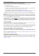
ABOUT YOUR WATER HEATER WATER HEATER APPLICATION This water heater is designed for use in a single family domestic dwelling for the purpose of heating potable water. Its use in an application other than this may shorten its life. MODEL TYPE The Rheem® continuous flow gas water heater model you have chosen is for outdoor installation only.
ABOUT YOUR WATER HEATER HOW HOT SHOULD THE WATER BE? The water heater may be installed with one or more user adjustable temperature controllers, which allow you to choose the most suitable temperature for your hot water needs (refer to “Temperature Control” on page 11). If a controller is not installed, the water heater heats the water to the preset outlet temperature setting.
ABOUT YOUR WATER HEATER HOTTER WATER INCREASES THE RISK OF SCALD INJURY This water heater can deliver water at temperatures which can cause scalding. Check the water temperature before use, such as when entering a shower or filling a bath or basin, to ensure it is suitable for the application and will not cause scald injury.
ABOUT YOUR WATER HEATER PRECAUTIONS The water heater must be maintained in accordance with the Owner’s Guide and Installation Instructions. Refer to “General Maintenance” on page 7, “Minor Maintenance Every Six Months” on page 7 and “Major Service Every Five Years” on page 7. If this water heater is to be used where an uninterrupted hot water supply is necessary for your application or business you should ensure that you have back-up redundancy within the hot water system design.
ABOUT YOUR WATER HEATER CIRCULATED HOT WATER FLOW AND RETURN SYSTEM A Rheem 874 series continuous flow water heater can be installed as part of a circulated hot water flow and return system in a building. Refer to “Circulated Hot Water Flow and Return System” on page 51 for further information and notes on this type of installation. GOING ON HOLIDAYS If you are going on holidays, it is not necessary to °C turn the water heater off.
ABOUT YOUR WATER HEATER FROST PROTECTION The water heater has a frost protection system. The frost protection system will protect the water heater from damage, by preventing ice forming in the waterways of the water heater, in the event of freezing conditions occurring. Notes: The frost protection system will be rendered inoperable if electrical power is not available at the water heater.
ABOUT YOUR WATER HEATER HOW DO I KNOW IF THE WATER HEATER IS INSTALLED CORRECTLY? Installation requirements are shown on pages 45 to 58. The water heater must be installed: by a qualified person, and in accordance with the installation instructions, and in compliance with Standards AS/NZS 3500.4, and either AS 5601 or AS/NZS 5601.1 as applicable under local regulations, and all local codes and regulatory authority requirements. The Gas installations Standards AS 5601 and AS/NZS 5601.
TEMPERATURE CONTROL CONTROLLERS The Rheem 874 and 876 series can be installed with Rheem controllers to enable the user to control the temperature of the delivered water from the outlet of the water heater. There are two families of Rheem controllers suitable for installation with this water heater. These are the standard controllers and the Deluxe controllers. Standard Controllers There are three types of standard controller.
88 X 10L TEMPERATURE CONTROL – STANDARD °C STANDARD CONTROLLER FUNCTIONS If one or more controllers are installed, at least one must °C be on for the water heater to operate. If all controllers are off, the water heater will only deliver cold water. 88 on / off ( ) button – This button must be pressed once to turn on the controller. X 10L 88 °C A controller cannot be turned on if water is flowing from a hot tap. X 10L To turn off a controller, press the on / off ( ) button once.
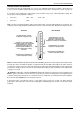
TEMPERATURE CONTROL – STANDARD STANDARD CONTROLLER Rheem priority light in use light up () button display panel °C water volume symbol down () button X 10L water volume operating light on / off operating light water volume button 88 °C on / off button controller type K = Kitchen B1 = Bathroom 110L B2 = Bathroom 2 X Note: water volume ( controller only.
TEMPERATURE CONTROL – STANDARD TEMPERATURE SETTINGS – STANDARD CONTROLLER The temperature settings of each type of controller are: Bathroom 1 & 2 37°C to 46°C (in 1°C increments), 48°C, 50°C Kitchen 37°C to 46°C (in 1°C increments), 48°C, 50°C*, 55°C**, 60°C * limited to 50°C on an 876 series model. ** NZ – limited to 55°C. Temperature settings 37 38 warm 39 40 41 42 43 44 average hot shower 45 46 48 hot 50 55 60 very hot The installation of a Bathroom controller(s) only (i.e.
TEMPERATURE CONTROL – STANDARD TEMPERATURE ADJUSTMENT – STANDARD CONTROLLER A controller must be on and have priority to be able to adjust the temperature setting. The temperature adjustment is made by pressing the up () button or down () button. The maximum temperature setting for the controllers are: Kitchen Bathroom 874 series 60°C – AU, 55°C – NZ 50°C 876 series 50°C 50°C Each press of the up () button will increase the temperature setting by one increment.
TEMPERATURE CONTROL – STANDARD KITCHEN CONTROLLER – STANDARD The Kitchen controller allows the user to select the temperature setting for the hot water to be used in the kitchen and laundry. It has a minimum temperature setting of 37°C and a maximum temperature setting of: 874 series 60°C – AU 876 series 50°C 55°C – NZ The Kitchen controller does not have priority if a Bathroom controller is on. Notes on the Kitchen controller: The controller cannot°C be turned on whilst a hot tap is open.
TEMPERATURE CONTROL – STANDARD To operate the Kitchen controller: 1. Turn off the Bathroom controller(s) If a temperature setting is displayed and the priority light is not glowing, it is necessary to turn off the Bathroom controller(s) to gain priority. Refer to°Cthe notes on the Kitchen controller on page 16. 88 X 10L 2. Turn on the Kitchen controller Press the on / off ( ) button. The on / off operating light and the priority light will both glow.
TEMPERATURE CONTROL – STANDARD BATHROOM CONTROLLERS – STANDARD The Bathroom controller(s) allows the user to select the temperature setting for the hot water to be used in the bathroom. They have a minimum temperature setting of 37°C and a maximum temperature setting of: 874 series 50°C 876 series 50°C The Bathroom controllers operate in tandem. Whenever an operation is selected on one Bathroom controller, it is also set on the other Bathroom controller.
TEMPERATURE CONTROL – STANDARD To operate a Bathroom controller: 1. Turn off the Kitchen controller If a temperature setting is displayed and the priority light is not glowing, it is advised to turn off the Kitchen controller. Refer to°Cthe notes on the Bathroom controllers on page 18. 88 X 10L 2. Turn on the Bathroom controller Press the on / off ( ) button. The on / off operating light and the priority light will both glow.
TEMPERATURE CONTROL – STANDARD WATER VOLUME FUNCTION The water volume function is designed to warn by an alarm (beeping sound), that a certain volume of water has been delivered from the water heater. It does not stop either the flow of or the heating of water. This function is useful if a bath is being filled, or measuring the water consumed by the use of a shower. The water volume function can only be set by the Kitchen controller. Refer to the notes on the water volume °C function on page 21.
88 °C TEMPERATURE CONTROL – STANDARD X 10L 5. Turn off the alarm Press the water volume ( ) button to turn off the alarm. The water volume operating light goes out and 0 x 10L is displayed momentarily on the controller. °C 42 X 10L The temperature setting of the controller with priority is then displayed. 6. Close the hot tap If it is a Bathroom controller which is in use and has priority, then it is advised to leave the controller on. Refer to the warning in the notes on page 18.
TEMPERATURE CONTROL – DELUXE 88 X 10L °C °C DELUXE CONTROLLER FUNCTIONS 88 If one or more Deluxe controllers are installed, at least one must be on or the Bath Fill function activated for °C the water heater to operate. If all Deluxe controllers and the Bath Fill function are off, the water heater will only deliver cold water. X 10L 88 88 X 10L °C on / off ( ) button – The on / off ( ) button must be pressed once to turn on the Deluxe controller.
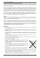
TEMPERATURE CONTROL – DELUXE bath fill water volume display panel – The selected bath fill water volume is displayed in litres on all Deluxe controllers. The selected bath fill water volume is displayed whenever the Bath Fill function is on (refer to “Bath-Fill Function” on page 32) or when the bath fill water volume is being adjusted and the Bath Fill function is off.
TEMPERATURE CONTROL – DELUXE VOICE PROMPT AND OPERATING TONE The Deluxe controllers have a series of voice prompts and operating tones which sound during certain operations. The voice prompts and operating tones sound from all Deluxe controllers, regardless of which Deluxe controller is being operated at the time.
TEMPERATURE CONTROL – DELUXE Adjusting the Volume of the Voice Prompt and Operating Tone The volume of the voice prompt and the operating tone can be adjusted to a level comfortable for you. The volume of the voice prompt and the operating tone can be adjusted independently of each other. The volume levels on a Deluxe controller are adjusted independently of another Deluxe controller.
TEMPERATURE CONTROL – DELUXE TEMPERATURE SETTINGS – DELUXE CONTROLLERS The temperature settings of each type of Deluxe controller are: Bathroom 1 & 2 Deluxe 37°C to 46°C (in 1°C increments), 48°C*, 50°C Kitchen Deluxe 37°C to 46°C (in 1°C increments), 48°C*, 50°C**, 55°C,*** 60°C * limited to 48°C when the Bath Fill function is set with 874 and 876 series models. ** limited to 50°C on an 876 series model. *** NZ – limited to 55°C.
TEMPERATURE CONTROL – DELUXE TEMPERATURE ADJUSTMENT – DELUXE CONTROLLERS A controller must be on with the PRIORITY indicator displayed to be able to adjust the temperature setting. The temperature adjustment is made by pressing the up () button or down () button. The minimum temperature setting for each type of controller is 37°C.
TEMPERATURE CONTROL – DELUXE KITCHEN CONTROLLER – DELUXE The Kitchen Deluxe controller allows the user to select the temperature setting for the hot water to be used in the kitchen and laundry. It has a minimum temperature setting of 37°C and a maximum temperature setting of: 874 series 60°C – AU 876 series 50°C 55°C – NZ The Kitchen Deluxe controller does not have priority (PRIORITY light is off) if a Bathroom Deluxe controller is on.
TEMPERATURE CONTROL – DELUXE To operate the Kitchen Deluxe controller: 1. Turn off the Bathroom Deluxe controller(s) If a temperature setting is displayed and the PRIORITY light is not glowing, it is necessary to turn off the Bathroom Deluxe controller(s) to gain priority. 88 °C °C BATH (l) Refer to the notes on the Kitchen Deluxe controller on page 28. X 10L 2. Turn on the Kitchen Deluxe controller Press the on / off ( ) button.
TEMPERATURE CONTROL – DELUXE BATHROOM CONTROLLERS – DELUXE The Bathroom Deluxe controller(s) allows the user to select the temperature setting for the hot water to be used in the bathroom. They have a minimum temperature setting of 37°C and a maximum temperature setting of: 874 series 50°C 876 series 50°C The Bathroom Deluxe controllers operate in tandem. Whenever an operation is selected on one Bathroom Deluxe controller, it is also set on the other Bathroom Deluxe controller.
TEMPERATURE CONTROL – DELUXE To operate a Bathroom Deluxe controller: 1. Turn off the Kitchen Deluxe controller If a temperature setting is displayed and the PRIORITY and on / off operating lights are not glowing, it is advised to turn off the Kitchen Deluxe controller. °C BATH (l) Refer °C to the notes on the Bathroom Deluxe controllers on page 30. 88 X 10L 2. Turn on the Bathroom Deluxe controller Press the on / off ( ) button.
88 TEMPERATURE CONTROL – DELUXE °C X 10L BATH FILL FUNCTION The Bath Fill function is designed to allow the water heater to deliver a selected volume of water at a selected temperature. The Bath Fill function commences when the bath fill ( ) button is on and a hot tap is opened. When the set volume has been delivered, the water flow from the water heater ceases and heating stops. It is also useful for controlling the water volume used by a shower or other application.
BATH (l) 5. 88 TEMPERATURE CONTROL – DELUXE °C Close the front panel on the Deluxe controller. X 10L 6. Turn on the Bath Fill function Press the bath fill ( Rheem ) button. On all Deluxe controllers: 7. The bath fill operating light will glow. The bath fill temperature setting will appear on the temperature display panel. The bath fill water volume will appear on the bath fill water volume display panel. The bath fill indicator light will glow.
TEMPERATURE CONTROL – DELUXE Bath Fill Function – Explanatory Notes To operate the Bath Fill function: 1. Turn off all Deluxe controllers It is advised to turn off all Deluxe controller(s) before activating the Bath Fill function. °C Refer to the notes on the Bathroom Deluxe controllers on page 30. BATH (l) The Deluxe controllers do not need to be on to set the bath fill temperature and bath fill water volume and to turn on the Bath Fill function. BATH FILL VOLUME 2.
TEMPERATURE CONTROL – DELUXE 4. Set the bath fill water volume Press the BATH FILL VOLUME up () button or the BATH FILL VOLUME down () button. While the bath fill water volume is displayed, each subsequent press of the BATH FILL VOLUME up () button or BATH FILL VOLUME down () button will change the water volume setting by 10 litres.
TEMPERATURE CONTROL – DELUXE 7. Open the hot tap. The operating light will glow on all Deluxe controllers. Measurement of the water flow at the water heater will commence when the hot tap is opened. 120 BATH (l) 40 °C Notes: If a second hot tap is opened when the Bath Fill function is turned on, the set bath fill water volume expected from the first hot tap will be reduced by the volume which flows through the second hot tap.
88 X 10L °C Turning Off Bath Fill Function During Its Operation The bath fill operation can be interrupted by pressing the bath fill ( °C operation. 88 °C TEMPERATURE CONTROL – DELUXE ) button before completion of the bath fill 88 X 10L If it is necessary to turn off the Bath Fill function before the operation is complete, during Step 7: X 10L Press the bath fill ( ) button. At this first press of the bath fill ( ) button: The operating light will go out.
TEMPERATURE CONTROL – DELUXE 88 Notes on the Bath Fill function: 88 °C °C X 10L The Bath Fill function can be set, turned on and turned off at any of the Deluxe controllers. The Deluxe controllers do not require to have priority (PRIORITY light glowing) or be on in order to set the bath fill water volume or bath fill temperature or to turn the bath fill ( ) button on.
TEMPERATURE CONTROL – DELUXE Opening a Second Hot Water Tap During Bath Fill Operation The bath fill water volume is measured as the water flows through the water heater. If more than one hot tap is open, the Bath Fill function will measure the total water volume drawn from all taps and the expected water volume from the first tap will be decreased. If the hot water supply should cease unexpectedly, check to see if the bath fill operating light is flashing.
TEMPERATURE CONTROL – DELUXE Operation of the Bath Fill function whilst a Deluxe Controller has priority It is recommended the Bath Fill function be set and operated with the Deluxe controllers turned off (refer to Step 1 on page 34).
WATER SUPPLIES This water heater must be installed in accordance with this advice to be covered by the Rheem warranty. This water heater is manufactured to suit the water conditions of most public reticulated water supplies. However, there are some known water chemistries which can have detrimental effects on the water heater and its operation and / or life expectancy. If you are unsure of your water chemistry, you may be able to obtain information from your local water supply authority.
SAVE A SERVICE CALL Check the items below before making a service call. You will be charged for attending to any condition or fault, which is not°C related to manufacture or failure of a part (refer to “Terms of the Rheem Warranty” on page 87). 88 X 10L NO DISPLAY ON THE CONTROLLER Is the controller turned on? Press the on / off ( ) button (refer to “Temperature Control” on pages 11 to 40).
SAVE A SERVICE CALL WATER FLOW FLUCTUATES More than one or two hot taps (12, 16 and 20 models) or more than two or three hot taps (24 and 26 models) in use at the same time may cause a decrease in the hot water flow from the taps. This can also be evident if the water heater has been installed as an in-series gas booster to a solar water heater and the solar heated water is at a low temperature.
SAVE A SERVICE CALL CLOUDS OF WHITE ‘VAPOUR’ FROM THE FLUE TERMINAL During the heating cycle, it is not unusual to see water vapour clouds steaming from the flue terminal, particularly on cold days. This is normal operation of the water heater. PRESSURE RELIEF VALVE DISCHARGING A pressure relief valve is incorporated into the water heater controls. This valve protects the water heater, by allowing water to escape, in the event of excessive pressure build-up in the waterways.
INSTALLATION – WATER HEATER THIS WATER HEATER IS FOR OUTDOOR INSTALLATION ONLY. THIS WATER HEATER IS NOT SUITABLE FOR POOL HEATING. Check the water heater is suitable for the gas type available. (refer to the rating label on the water heater) INSTALLATION STANDARDS The water heater must be installed: by a qualified person, and in accordance with the installation instructions, and in compliance with Standards AS/NZS 3500.4, and either AS 5601 or AS/NZS 5601.
INSTALLATION – WATER HEATER This water heater must be installed vertically upright with the water, gas and power connections on the underside, pointing toward the ground. The back of the water heater can be either against a wall or supported by a frame. Note: The water heater must be well secured to the wall or frame using two fasteners each at the top and bottom of the unit (refer to pages 54 and 55 for the weight of the water heater and mounting hole positions).
INSTALLATION – WATER HEATER INSTALLATION WITHIN A COVERED AREA The water heater must be located such that the installation meets the requirements of either AS 5601 or AS/NZS 5601.1 as applicable under local regulations. There must be sufficient ventilation so the water heater has an adequate supply of combustion air and the flue products are dispersed safely.
INSTALLATION – WATER HEATER RECESS INSTALLATION The water heater can be installed recessed into a wall. A recess box (Rheem AU – Part 299247, NZ – Parts 318994 [recess box enclosure kit] and 318995 [recess box door kit]) is available for such an installation. Refer to the installation instructions which accompany the recess box kit for information on its installation. An additional rating label is supplied attached to the inside of the front cover of the water heater.
INSTALLATION – WATER HEATER HOT WATER DELIVERY This water heater can deliver water at temperatures which can cause scalding. It is necessary and we recommend that a temperature limiting device be fitted between an 874 series water heater and the hot water outlets in any ablution and public areas such as a bathroom, ensuite or public amenities, to reduce the risk of scalding.
INSTALLATION – WATER HEATER Where a temperature limiting device is installed adjacent to the in-series gas booster, the cold water line to the temperature limiting device can be branched off the cold water line either before or after the isolation valve and pressure limiting valve to the solar storage tank, but it MUST BE before the non-return valve prior to an open circuit system.
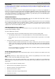
INSTALLATION – WATER HEATER CIRCULATED HOT WATER FLOW AND RETURN SYSTEM A Rheem 874 series continuous flow water heater can be installed as part of a circulated hot water flow and return system in a building. Notes: the preset outlet temperature setting of the water heater must be set to at least 60°C. Water should not be circulated from a water heater with a temperature setting of less than 60°C.
INSTALLATION – WATER HEATER Circulated Hot Water Flow and Return Continuous Flow Gas Water Heater from solar storage tank Circulated Hot Water Flow and Return In-series Gas Booster as part of a Solar Water Heater Installation REDUCING HEAT LOSSES The hot water line from the water heater and the pipe work between the solar storage tank, if one is installed, and the in-series gas booster must be insulated in accordance with the requirements of AS/NZS 3500.4.
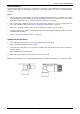
INSTALLATION – WATER HEATER WATER TEMPERATURE DIAGRAMS Note: NZ - Kitchen Controller max setting is 55°C 874 Series - Kitchen and Bathroom Controllers 876 Series – Kitchen and Bathroom Controllers Note: NZ - Kitchen Controller max setting is 55°C 874 Series - Kitchen Controller Only 876 Series - Kitchen Controller Only 874 Series - Bathroom Controllers Only 876 Series - Bathroom Controllers Only 874 Series - No Controllers 876 Series - No Controllers Notes: Temperature Limiting Devices – refer
INSTALLATION – WATER HEATER TECHNICAL DATA Model 874812 876812 874816, 874T16 876T16 874820 876820 874824 874826, 874T26 876826, 876T26 Rated delivery - (@ 40°C rise) litres / min 7.5 10 12.5 15 16.2 Recovery - (@ 25°C rise) litres / min 12 16 20 24 26 kg 16 16 16 16 16 Mass Empty (unpackaged) Gas Details Min. Gas Pressure (kPa) Hourly Gas Consumption (MJ) Max.
INSTALLATION – WATER HEATER DIMENSIONS – WATER HEATER 55
INSTALLATION – WATER HEATER DIMENSIONS – STANDARD CONTROLLERS Kitchen Controller (Standard) Bathroom Controller (Standard) 56
INSTALLATION – WATER HEATER DIMENSIONS – DELUXE CONTROLLERS Deluxe Controller – Cover Closed Deluxe Controller – Cover Open 57
INSTALLATION – WATER HEATER TYPICAL INSTALLATION – OUTDOOR LOCATION 58
CONNECTIONS – PLUMBING All plumbing work must be carried out by a qualified person and in compliance with the Standard AS/NZS 3500.4 and all local codes and regulatory authority requirements. In New Zealand the installation must conform to Clauses G11, G12 and H1 of the New Zealand Building Code. All gas work must be carried out by a qualified person and in compliance with the Standard AS 5601 or AS/NZS 5601.1, as applicable under local regulations, and all local codes and regulatory authority requirements.
CONNECTIONS – PLUMBING IN-SERIES BOOSTER The pipe work between the solar storage tank (if one is installed) and the in-series gas booster has a minimum recommended pipe size of DN20, MUST BE of copper and be fully insulated with a closed cell type insulation or equivalent in accordance with the requirements of AS/NZS 3500.4. The insulation must be weatherproof and UV resistant if exposed. The insulation must be fitted up to the connections on both the solar storage tank and the in-series gas booster.
CONNECTIONS – ELECTRICAL All electrical work and permanent wiring must be carried out by a qualified person and in accordance with the Wiring Rules AS/NZS 3000 and all local codes and regulatory authority requirements. Warning: Temperature controllers must not be fitted to this water heater (874 series) if it is installed as an in-series gas booster with a solar water heater system because water at a temperature much higher than the controller setting can be delivered.
CONNECTIONS – ELECTRICAL WIRING DIAGRAM Wiring Diagram – 874, 876 Series 812, 816, T16, 820, 824, 826, T26 Models 62
EZ LINK SYSTEM DUAL INSTALLATION The EZ Link™ system is designed to electronically control two continuous flow gas water heaters and have them operate as one. One or both water heaters may be in operation, depending upon the hot water demand. The second water heater will only operate when the hot water demand exceeds the capacity of the first water heater to supply.
EZ LINK SYSTEM DUAL INSTALLATION DUAL INSTALLATION The two water heaters can be installed side by side with minimal clearance between them. Rheem 874 and 876 series 812, 816, T16, 820, 824, 826 and T26 models are certified for installation with an exemption from the 300 mm minimum clearance requirements between flue terminals, as stated in AS 5601, clause 5.13.6.5 and AS/NZS 5601.1, clause 6.9.3. Install two water heaters of the same model in a parallel plumbing arrangement.
EZ LINK SYSTEM DUAL INSTALLATION EZ LINK CABLE CONNECTION The references in steps 8 to 11 are to the ‘Control Board with EZ Link Connection’ diagram on page 66. To connect the EZ Link cable to the water heaters: 1. Close any hot taps and ensure the burners on both water heaters are not operating. 2. Switch off the electrical supply at the power outlet to each water heater. 3.
88 X 10L EZ LINK SYSTEM DUAL INSTALLATION 17. Turn on the controller by pressing the on / off ( ) button, if one is installed. The on / off operating light and the priority light will both glow. 18. Check to ensure the flow from each connected hot tap is sufficient to operate a water heater. Open each hot tap independently. One of the water heaters will operate automatically. The minimum operating flow rate for each water heater is 2.0 Litres per minute. 19.
EZ LINK SYSTEM DUAL INSTALLATION Typical Two Unit Manifold with EZ Link Connection 874 and 876 series 812, 816, T16, 820, 824, 826 and T26 models 67
INSTALLATION – CONTROLLERS CONTROLLERS The Rheem 874 and 876 series can be installed with Rheem controllers to enable the user to control the temperature of the delivered water from the outlet of the water heater. There are two families of Rheem controllers suitable for installation with this water heater. These are the standard controllers and the Deluxe controllers. Standard Controllers There are three types of standard controller.
INSTALLATION – CONTROLLERS Location – The controllers must be installed in dry, shaded and clean locations. Do not install the controllers: Near a heat source, such as a cook top, stove or oven. Heat, steam and smoke will interfere with the electronic components of the controllers. In direct sunlight. In or near a wet area. The controllers are not waterproof. Water may damage the controllers. Outdoors. The controllers are not weatherproof.
INSTALLATION – CONTROLLERS Wiring installation: 1. Penetrate the wall with a 30-35 mm hole at the controller location. 2. Install the Kitchen controller cable between the location of the controller and the water heater. 3. Remove the base plate from the controller. 4. Draw the cable through the central hole in the base plate. 5. Fix the base plate to the wall using suitable screws and wall anchors. Ensure the projections in the base plate are pointing upwards. 6.
INSTALLATION – CONTROLLERS If it is necessary to have an exposed wiring installation, follow this procedure omitting Steps 1 and 4, and make an opening in the thin section in the underside of the controller to accommodate the cable (as shown in the diagram), prior to Step 6.
INSTALLATION – CONTROLLERS BATHROOM 1 AND BATHROOM 2 CONTROLLERS If only one Bathroom controller is to be installed, the standard Bathroom 1 Controller (Rheem AU - Part 299854, NZ - Part A299851) or the Bathroom 1 Deluxe controller (Rheem AU - Part 299862, NZ - Part A299862) must be used.
INSTALLATION – CONTROLLERS Wiring installation: 1. Penetrate the wall with a 30-35 mm hole at the controller location. 2. Install the supplied cable between the location of the controller and the water heater. 3. Remove the base plate from the controller. 4. Peel off one side of the adhesive paper from the foam packing and adhere to the back face of the base plate. This is the side without the projections. 5. Peel off the remaining adhesive paper from the foam packing. 6.
INSTALLATION – CONTROLLERS CONNECTING THE CONTROLLER(S) TO THE WATER HEATER To connect the controller(s) to the water heater: 1. Ensure the electrical supply to the water heater is switched off. 2. Unscrew and gently flip down the electrical cover on the underside of the water heater. 3. Draw the cable(s) through the electrical cover. 4. Connect a cable lug from each cable to each of the remote controller terminals. Each cable has two cable lugs.
COMMISSIONING All water heaters are tested and adjusted before dispatch from the factory, however further adjustments may become necessary because of local conditions. TO TURN ON THE WATER HEATER Open all of the hot taps in the house (don’t forget the shower). Open the cold water isolation valve fully at the inlet to the water heater. Air will be forced out of the taps. Close each tap as water flows freely from it. Check the pipe work for leaks. Open the gas isolation valve fully.
COMMISSIONING Gas Inlet Test Point Pressure To check the gas inlet pressure: 1. Close any hot taps and ensure the burners are not operating. 2. Close the gas isolation valve at the gas inlet to the water heater. 3. Locate the gas inlet test point on the gas connection to the water heater. Remove the test point screw and washer from the test point orifice. Connect the manometer. 4. Open the gas isolation valve fully at the gas inlet to the water heater. 5.
COMMISSIONING BURNER GAS PRESSURE It is necessary to check the burner gas pressure at both the minimum and maximum operational settings. To check and if necessary adjust the operational gas pressures, the electrical supply to the water heater must be switched on, the burners ignited and hot water must be flowing from a hot tap. Warning: The removal of the front panel will expose 240 volt wiring. Take care not to touch wiring terminals.
COMMISSIONING Notes: If the burners extinguish and an error code 11 or 12 starts to flash on the LED display: release the MIN and adjuster buttons close the hot tap clear the error code (refer to “Clearing Error Code” on page 78) recommence the procedure from Step 9. If the adjuster button is released before Step 14, clear any error code (if displayed) and recommence the procedure from Step 9.
COMMISSIONING PRESET OUTLET TEMPERATURE SETTING The factory preset outlet temperature setting of the water heater is: 874 series 60°C – AU, 55°C – NZ 876 series 50°C If a temperature controller is connected to the water heater, this will override the preset outlet temperature setting and the maximum temperature setting will be: Maximum Outlet Temperature Kitchen controller connected Bathroom controller only connected 874 series 876 series 60°C – AU, 55°C – NZ 50°C 50°C 50°C It is usually
COMMISSIONING Warning: The removal of the front panel will expose 240 volt wiring. Take care not to touch wiring terminals. The adjustment must be carried out by a qualified person. Warning: This procedure will involve the adjustment of dip switches. Adjustment of a dip switch should only be made with an insulated tool. To check or adjust the preset outlet temperature setting: 1. Switch off the electrical supply at the power outlet to the water heater. 2.
COMMISSIONING OUTLET TEMPERATURE COMPENSATION ADJUSTMENT The outlet temperature compensation adjustment function is only applicable to: AU – Australian 876 series 812, T16, 820, 824, 826 and T26 model water heaters The maximum outlet temperature may be adjusted to compensate for temperature losses in the pipe work between the water heater outlet and sanitary fixtures. The 876 series is available in Australia only.
COMMISSIONING Disconnecting a Temperature Controller(s) To disconnect the temperature controller(s): 1. Switch off the electrical supply at the power outlet to the water heater. 2. Unscrew and gently flip down the electrical cover on the underside of the water heater. 3. Loosen the terminal screws to release the cable lugs. 4. Withdraw the cable lugs, ensuring they are well clear of the terminals.
COMMISSIONING 11. Switch DIP switch 3 to the on (up) position on the PCB. The current outlet temperature setting will show on the LED display. 12. AU – 876 series: Press the MAX button once to increase the outlet temperature setting to the next increment. The MAX button is located below the DIP switches and adjuster button, and above the MIN button. Each press of the MAX button will increase the outlet temperature setting by one increment. The outlet temperature setting will show on the LED display.
COMMISSIONING 17. NZ – 874 series: if the water temperature is still above 55°C and requires to be decreased, repeat steps 11, 13 and 14, followed by steps 2 to 5 until an acceptable water temperature not exceeding 55°C is measured at the same hot tap. if the water temperature is below 55°C then; switch DIP switch 3 to the on (up) position on the PCB. The outlet temperature setting will show on the LED display.
DRAINING THE WATER HEATER To drain the water heater: Turn off the water heater (refer to “Turn Off The Water Heater” on page 84). Open a hot tap (preferably the shower outlet). Unscrew the two drain plugs, one each at the cold water inlet and hot water outlet, on the underside of the water heater. Water will drain from the water heater. When water stops flowing from the water heater, close the hot tap.
This page is intentionally blank.
RHEEM CONTINUOUS FLOW GAS WATER HEATER WARRANTY – AUSTRALIA AND NEW ZEALAND ONLY 874, 876 SERIES 812, 816, T16, 820, 824, 826, T26 MODELS 1. THE RHEEM WARRANTY – GENERAL 1.1 This warranty is given in Australia by Rheem Australia Pty Limited ABN 21 098 823 511 of 1 Alan Street, Rydalmere New South Wales, and in New Zealand by Rheem New Zealand Limited of 475 Rosebank Road Avondale Auckland 1026, the suppliers of Rheem continuous flow gas water heaters. 1.
RHEEM CONTINUOUS FLOW GAS WATER HEATER WARRANTY – AUSTRALIA AND NEW ZEALAND ONLY 874, 876 SERIES 812, 816, T16, 820, 824, 826, T26 MODELS 3. WHAT IS COVERED BY THE RHEEM WARRANTY FOR THE WATER HEATERS DETAILED IN THIS DOCUMENT 3.