
User Manual
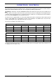
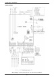


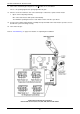


Table Of Contents
- Contents
- About Your Water Heater
- Water Heater Application
- Model Type
- Mains Pressure
- Water Heater Operation
- Reduced Hot Water Flow When Heat Exchanger Is Cold
- Gas Boosting For A Solar Water Heater
- How Hot Should The Water Be?
- Hotter Water Increases The Risk Of Scald Injury
- Safety
- Warnings
- Precautions
- General Maintenance
- Minor Maintenance Every Six Months
- Major Service Every Five Years
- Circulated Hot Water Flow And Return System
- Going On Holidays
- To Turn Off The Water Heater
- To Turn On The Water Heater
- Frost Protection
- Draining The Water Heater
- How Do I Know If The Water Heater Is Installed Correctly?
- Victorian Customers
- Does The Water Chemistry Affect The Water Heater?
- How Long Will The Water Heater Last?
- Temperature Control
- Temperature Control – Standard
- Temperature Control – Deluxe
- Deluxe Controller Functions
- Deluxe Controller
- Voice Prompt And Operating Tone
- Assistance Call Function
- Temperature Settings – Deluxe Controllers
- Temperature Adjustment – Deluxe Controllers
- Kitchen Controller – Deluxe
- Bathroom Controllers – Deluxe
- Bath Fill Function
- Bath Fill Function – Brief Guide
- Bath Fill Function – Explanatory Notes
- Turning Off Bath Fill Function During Its Operation
- Notes on the Bath Fill function:
- Opening a Second Hot Water Tap During Bath Fill Operation
- Early Completion of Bath Fill Operation
- Interrupting Bath Fill Operation
- Operation of the Bath Fill function whilst a Deluxe Controller has priority
- Water Supplies
- Save A Service Call
- No Display On The Controller
- Cold Water From The Hot Tap
- Water Is Too Hot Or Not Hot Enough
- Reduced Hot Water Flow When Heat Exchanger Is Cold
- No Water From The Hot Tap
- Water Flow Fluctuates
- Gas Booster Operating Too Frequently
- Fan Continues To Run After Water Heater Operation Stops
- Clouds Of White ‘Vapour’ From The Flue Terminal
- Pressure Relief Valve Discharging
- Error Code
- Higher Than Expected Gas Bills
- Installation – Water Heater
- Installation Standards
- Water Heater Application
- Water Heater Location
- Installation Within A Covered Area
- Pipe Cover
- Recess Installation
- Frost Protection
- Mains Water Supply
- Hot Water Delivery
- Circulated Hot Water Flow And Return System
- Reducing Heat Losses
- Water Temperature Diagrams
- Technical Data
- Dimensions – Water Heater
- Dimensions – Standard Controllers
- Dimensions – Deluxe Controllers
- Typical Installation – Outdoor Location
- Connections – Plumbing
- Connections – Electrical
- EZ LINK System Dual Installation
- Installation – Controllers
- Commissioning
- Draining The Water Heater
- Rheem Continuous Flow Gas Water Heater Warranty – Australia and New Zealand Only
- 1. The Rheem Warranty – General
- 2. Terms Of The Rheem Warranty And Exclusions To It
- 3. What Is Covered By The Rheem Warranty For The Water Heaters Detailed In This Document
- 4. Entitlement To Make A Claim Under This Warranty
- 5. How To Make A Claim Under This Warranty
- 6. The Australian Consumer Law

EZ LINK SYSTEM DUAL INSTALLATION
64
DUAL INSTALLATION
The two water heaters can be installed side by side with minimal clearance between them. Rheem 874 and
876 series 812, 816, T16, 820, 824, 826 and T26 models are certified for installation with an exemption from
the 300 mm minimum clearance requirements between flue terminals, as stated in AS 5601, clause 5.13.6.5
and AS/NZS 5601.1, clause 6.9.3.
Install two water heaters of the same model in a parallel plumbing arrangement. It is good practice, but not
essential, to install the two water heaters in an Equa-Flow
®
plumbing arrangement. There are basic installation
requirements which must be followed:
1. The pipe work must be sized to meet the requirements of both AS/NZS 3500.4 and the application. It is
recommended to use minimum DN25 pipe for the cold water line, cold and hot headers and hot water line
and DN20 for the cold and hot water branch lines of each water heater.
2. A full flow gate valve or ball valve must be installed on the cold water line to the system. A non-return
valve or stop tap must not be installed.
3. A full flow gate valve or ball valve (not a stop tap) should be installed on both the cold water branch and
hot water branch of each water heater.
4. An isolation valve must be installed on the gas branch of each water heater.
5. Non-return valves or pressure limiting valves must not be installed on the branch lines to the water heaters.
6. All fittings, valves and branch lines should be matched sets to each of the water heaters.
7. Sufficient space must be left to enable access, servicing or removal of either water heater.
A second rating label is attached to the inside of the front cover. This can be referenced to determine details
of the left hand water heater.
Refer to the ‘Typical Two Unit Manifold with EZ Link Connection’ diagram on page 67 for installation and plant
layout details.
TEMPERATURE CONTROLLER
A temperature controller(s) may be installed but is not required to be installed on the Rheem 874 and 876 series
812, 816, T16, 820, 824, 826 and T26 model water heaters with the EZ Link system. The controller can be
either a standard or Deluxe controller.
Connect a temperature controller to one only of the two water heaters. Up to three temperature controllers of
the same family can be installed to this water heater. Refer to “Installation – Controllers” on page 68.
The water heater connected with the temperature controller(s) will become the ‘master’ water heater. The
installed temperature controller(s) will control the temperature and functionality of both water heaters.
The maximum outlet temperature of the water heaters will be limited by the maximum temperature setting of
the temperature controller.
A temperature controller should not be installed if two 874 series 812, 816, T16, 820, 824, 826 or T26 model
water heaters have been EZ Linked together and they are part of a circulated hot water flow and return system
in a building. Refer to “Circulated Hot Water Flow And Return System” on page 51.