
User Manual
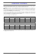
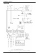


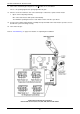


Table Of Contents
- Contents
- About Your Water Heater
- Water Heater Application
- Model Type
- Mains Pressure
- Water Heater Operation
- Reduced Hot Water Flow When Heat Exchanger Is Cold
- Gas Boosting For A Solar Water Heater
- How Hot Should The Water Be?
- Hotter Water Increases The Risk Of Scald Injury
- Safety
- Warnings
- Precautions
- General Maintenance
- Minor Maintenance Every Six Months
- Major Service Every Five Years
- Circulated Hot Water Flow And Return System
- Going On Holidays
- To Turn Off The Water Heater
- To Turn On The Water Heater
- Frost Protection
- Draining The Water Heater
- How Do I Know If The Water Heater Is Installed Correctly?
- Victorian Customers
- Does The Water Chemistry Affect The Water Heater?
- How Long Will The Water Heater Last?
- Temperature Control
- Temperature Control – Standard
- Temperature Control – Deluxe
- Deluxe Controller Functions
- Deluxe Controller
- Voice Prompt And Operating Tone
- Assistance Call Function
- Temperature Settings – Deluxe Controllers
- Temperature Adjustment – Deluxe Controllers
- Kitchen Controller – Deluxe
- Bathroom Controllers – Deluxe
- Bath Fill Function
- Bath Fill Function – Brief Guide
- Bath Fill Function – Explanatory Notes
- Turning Off Bath Fill Function During Its Operation
- Notes on the Bath Fill function:
- Opening a Second Hot Water Tap During Bath Fill Operation
- Early Completion of Bath Fill Operation
- Interrupting Bath Fill Operation
- Operation of the Bath Fill function whilst a Deluxe Controller has priority
- Water Supplies
- Save A Service Call
- No Display On The Controller
- Cold Water From The Hot Tap
- Water Is Too Hot Or Not Hot Enough
- Reduced Hot Water Flow When Heat Exchanger Is Cold
- No Water From The Hot Tap
- Water Flow Fluctuates
- Gas Booster Operating Too Frequently
- Fan Continues To Run After Water Heater Operation Stops
- Clouds Of White ‘Vapour’ From The Flue Terminal
- Pressure Relief Valve Discharging
- Error Code
- Higher Than Expected Gas Bills
- Installation – Water Heater
- Installation Standards
- Water Heater Application
- Water Heater Location
- Installation Within A Covered Area
- Pipe Cover
- Recess Installation
- Frost Protection
- Mains Water Supply
- Hot Water Delivery
- Circulated Hot Water Flow And Return System
- Reducing Heat Losses
- Water Temperature Diagrams
- Technical Data
- Dimensions – Water Heater
- Dimensions – Standard Controllers
- Dimensions – Deluxe Controllers
- Typical Installation – Outdoor Location
- Connections – Plumbing
- Connections – Electrical
- EZ LINK System Dual Installation
- Installation – Controllers
- Commissioning
- Draining The Water Heater
- Rheem Continuous Flow Gas Water Heater Warranty – Australia and New Zealand Only
- 1. The Rheem Warranty – General
- 2. Terms Of The Rheem Warranty And Exclusions To It
- 3. What Is Covered By The Rheem Warranty For The Water Heaters Detailed In This Document
- 4. Entitlement To Make A Claim Under This Warranty
- 5. How To Make A Claim Under This Warranty
- 6. The Australian Consumer Law
EZ LINK SYSTEM DUAL INSTALLATION
65
EZ LINK CABLE CONNECTION
The references in steps 8 to 11 are to the ‘Control Board with EZ Link Connection’ diagram on page 66. To
connect the EZ Link cable to the water heaters:
1. Close any hot taps and ensure the burners on both water heaters are not operating.
2. Switch off the electrical supply at the power outlet to each water heater.
3. Remove the top and bottom cover strips to gain access to the front panel screws by pressing on the two
ridged finger points and gently pulling forward.
4. Remove the screws holding the front panel to the jacket on each water heater.
5. Gently disengage the front panel and pull forward to remove from each water heater.
6. Remove the screw securing the Control Board on each water heater. Discard the screws.
7. Gently pull forward the Control Board on each water heater to improve access to the cable connector.
8. Connect one end of the EZ Link cable to the first water heater.
If a controller(s) is connected to one of the water heaters, then this is the ‘master’ or ‘first’ water heater.
Draw the cable through the cable grommet on the underside of the water heater.
Plug the cable into the four pin connector marked “E” in the mid right-hand side of the Control Board
(refer to the Control Board diagram).
The connector will only fit one way.
Press until the connector snaps into place.
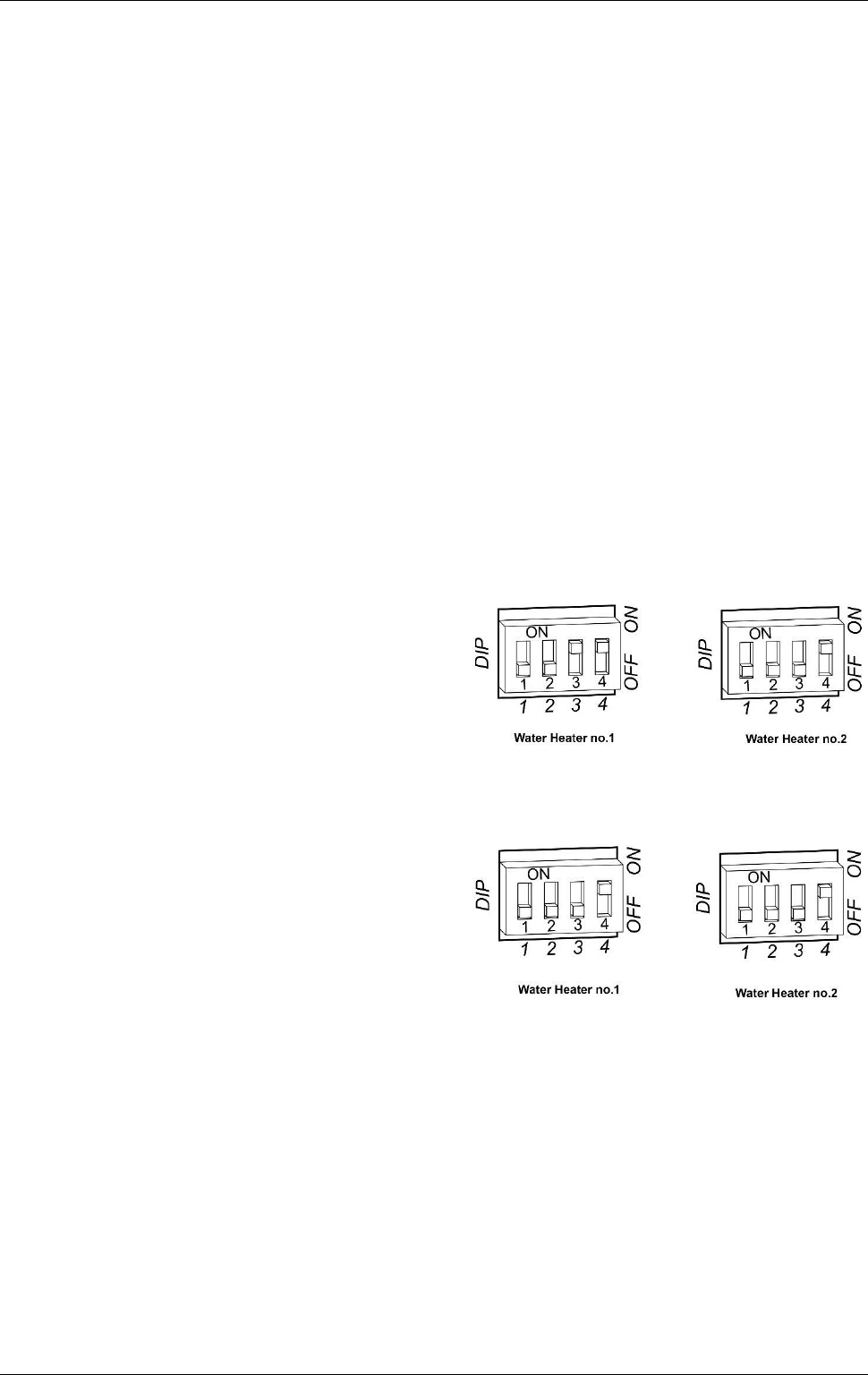
9. Switch DIP switch 4 to the on (up) position on the
first water heater (refer to the Control Board
diagram).
If a temperature controller is not installed, then
also switch DIP switch 3 to the on (up) position
on the first water heater.
10. Connect the other end of the EZ Link cable to the
second water heater.
Draw the cable through the cable grommet on
the underside of the water heater.
Plug the cable into the connector marked “E” in
the mid right-hand side of the Control Board
(refer to the Control Board diagram).
The connector will only fit one way.
Press until the connector snaps into place.
11. Switch DIP switch 4 to the on (up) position on the
second water heater (refer to the Control Board
diagram).
12. Refit the control board and secure the EZ Link cable with the clamp and screw provided to the top right of
the Control Board to each water heater. This also secures the Control Board in position.
13. Refit the front panel and screws to each water heater.
14. Refit the cover strips to the top and bottom of the front panel by inserting the two posts into the two
recesses and gently pushing into position.
15. Check the main gas isolation valve and the isolation valves at the gas inlet to each water heater are fully
open.
16. Switch on the electrical supply at the power outlets to the water heaters.
dip switch settings
without temperature controller
dip switch settings
with temperature controller connected