
User Manual
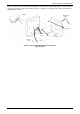
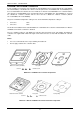
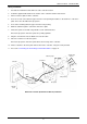
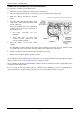


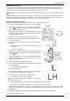


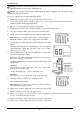
Table Of Contents
- Contents
- About Your Water Heater
- Water Heater Application
- Model Type
- Mains Pressure
- Water Heater Operation
- Reduced Hot Water Flow When Heat Exchanger Is Cold
- Gas Boosting For A Solar Water Heater
- How Hot Should The Water Be?
- Hotter Water Increases The Risk Of Scald Injury
- Safety
- Warnings
- Precautions
- General Maintenance
- Minor Maintenance Every Six Months
- Major Service Every Five Years
- Circulated Hot Water Flow And Return System
- Going On Holidays
- To Turn Off The Water Heater
- To Turn On The Water Heater
- Frost Protection
- Draining The Water Heater
- How Do I Know If The Water Heater Is Installed Correctly?
- Victorian Customers
- Does The Water Chemistry Affect The Water Heater?
- How Long Will The Water Heater Last?
- Temperature Control
- Temperature Control – Standard
- Temperature Control – Deluxe
- Deluxe Controller Functions
- Deluxe Controller
- Voice Prompt And Operating Tone
- Assistance Call Function
- Temperature Settings – Deluxe Controllers
- Temperature Adjustment – Deluxe Controllers
- Kitchen Controller – Deluxe
- Bathroom Controllers – Deluxe
- Bath Fill Function
- Bath Fill Function – Brief Guide
- Bath Fill Function – Explanatory Notes
- Turning Off Bath Fill Function During Its Operation
- Notes on the Bath Fill function:
- Opening a Second Hot Water Tap During Bath Fill Operation
- Early Completion of Bath Fill Operation
- Interrupting Bath Fill Operation
- Operation of the Bath Fill function whilst a Deluxe Controller has priority
- Water Supplies
- Save A Service Call
- No Display On The Controller
- Cold Water From The Hot Tap
- Water Is Too Hot Or Not Hot Enough
- Reduced Hot Water Flow When Heat Exchanger Is Cold
- No Water From The Hot Tap
- Water Flow Fluctuates
- Gas Booster Operating Too Frequently
- Fan Continues To Run After Water Heater Operation Stops
- Clouds Of White ‘Vapour’ From The Flue Terminal
- Pressure Relief Valve Discharging
- Error Code
- Higher Than Expected Gas Bills
- Installation – Water Heater
- Installation Standards
- Water Heater Application
- Water Heater Location
- Installation Within A Covered Area
- Pipe Cover
- Recess Installation
- Frost Protection
- Mains Water Supply
- Hot Water Delivery
- Circulated Hot Water Flow And Return System
- Reducing Heat Losses
- Water Temperature Diagrams
- Technical Data
- Dimensions – Water Heater
- Dimensions – Standard Controllers
- Dimensions – Deluxe Controllers
- Typical Installation – Outdoor Location
- Connections – Plumbing
- Connections – Electrical
- EZ LINK System Dual Installation
- Installation – Controllers
- Commissioning
- Draining The Water Heater
- Rheem Continuous Flow Gas Water Heater Warranty – Australia and New Zealand Only
- 1. The Rheem Warranty – General
- 2. Terms Of The Rheem Warranty And Exclusions To It
- 3. What Is Covered By The Rheem Warranty For The Water Heaters Detailed In This Document
- 4. Entitlement To Make A Claim Under This Warranty
- 5. How To Make A Claim Under This Warranty
- 6. The Australian Consumer Law

COMMISSIONING
80
Warning: The removal of the front panel will expose 240 volt wiring. Take care not to touch wiring terminals.
The adjustment must be carried out by a qualified person.
Warning: This procedure will involve the adjustment of dip switches. Adjustment of a dip switch should
only be made with an insulated tool.
To check or adjust the preset outlet temperature setting:
1. Switch off the electrical supply at the power outlet to the water heater.
2. Remove the top and bottom cover strips to gain access to the front panel screws by pressing on the two
ridged finger points and gently pulling forward.
3. Remove the screws holding the front panel to the jacket.
4. Gently disengage the front panel and pull forward to remove from the water heater.
5. Close the cold water isolation valve at the inlet to the water heater.
6. Switch on the electrical supply at the power outlet to the water heater.
Note: Wait five (5) seconds for the electronic system to initialise.
7. Switch DIP switches 3 and 4 to the on (up) position on the PCB.
The current preset outlet temperature setting will show on the LED
display.
If the temperature displayed on the LED display is the desired preset
outlet temperature setting, then proceed to step 9, as no further
adjustment is necessary.
8. Press the MAX button to increase or the MIN button to decrease the
preset outlet temperature setting.
Each press of the MAX or MIN button will increase or decrease the
preset temperature by one increment.
The MAX and MIN buttons are located below the DIP switches and
adjuster button.
874 series
The increments are 38°C, 40°C, 42°C, 43°C, 45°C*, 48°C, 50°C,
55°C, 60°C**, 65°C, 70°C, 75°C.
* 45°C – NZ models only ** 60 °C – AU models only
876 series
The increments are 38°C, 40°C, 42°C, 43°C, 45°C, 48°C, 50°C.
9. Switch DIP switches 3 and 4 to the off (down) position.
The LED display will go blank.
Note: Wait five (5) seconds for the setting to be saved. The preset
outlet temperature setting is now set.
10. Switch off the electrical supply at the power outlet to the water heater.
11. Refit the front panel and screws to the water heater.
12. Refit the cover strips to the top and bottom of the front panel by inserting the two posts into the two
recesses and gently pushing into position.
13. Open the cold water isolation valve fully at the inlet to the water heater.
14. Switch on the electrical supply at the power outlet to the water heater.