
Specifications
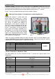

TM025 Rheem Heat Pump Service Instructions REV: B
Date of Issue: 02/08/07
This document is stored and maintained electronically by
Service. All printed copies not bearing this statement in RED are deemed “uncontrolled”.
28
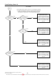
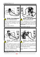
Component Tests 12 – 15
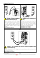
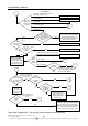
Tests 12 Test 13
Warning – ‘Live’ equipment wear
Personal Protective Equipment
when conducting this test.
Remove the compressor electrical access
cover and using a multimeter on the AC
voltage scale, measure between the red
and blue wires.
Normal voltage is 240 volts.
Warning – ‘Live’ equipment wear
Personal Protective Equipment
when conducting this test.
Using a multimeter on the AC voltage
scale, measure between the control board
compressor output terminal and the top
terminal of the heat pump module terminal
block (Neutral).
Normal voltage is 240 volts.
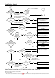
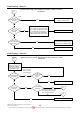
Test 14 Test 15
Warning - Ensure power is
isolated before conducting this
test.
Remove the compressor electrical access
cover and mark and disconnect terminal
wiring. Using a multimeter on the ohms
scale, measure between the compressor
terminals. The following run and start
winding results should be obtained.
(Run) Red & Blue terminals – 2.2 ohms
(Start) Red & Black terminals – 3.2 ohms
Warning - Ensure power is
isolated before conducting this
test.
Disconnect the wiring to the compressor
capacitor and using a multimeter on the
capacitance (µF) scale measure between
the two capacitor terminals.
Normal capacitance is 35 micro Farads
(35µF).