
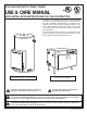
Instructions / Assembly

3
Read and Review this entire Manual with special em-
phasis on the Installation Section (Pages 3 - 6) and
Operation Section (Pages 7 - 8) prior to any installa-
tion work.
LOCAL INSTALLATION REGULATIONS—This water heater
must be installed in accordance with these instruc-
tions, local codes, utility company requirements, and/
or in the absence of local codes, the latest edition of the
American National Standard / National Electrical Code.
A copy of which can be purchased from the National Fire
Protection Association, 1 Batterymarch Park, Quincy, MA
02269 as booklet NFPA 70.
LOCATION
A. The water heater should be installed in a clean, dry
location as close as practical to the area of greatest hot
water demand. Long hot water lines should be insulated
to conserve water and energy. The water heater and
water lines should be protected from exposure to freez-
ing temperatures. DO NOT install the water heater in an
outdoor, unprotected area.
B. The water heater should not be located in an area
where leakage of the tank or connections will result in
damage to the area adjacent to it or to lower floors of
the structure. When such areas cannot be avoided, it
is recommended that a suitable catch pan, adequately
drained, be installed under the water heater.
NOTE: Auxiliary catch pan installation MUST conform the
applicable local codes.
C. FOR THE TANK TYPE MODELS, the minimum dis-
tance to provide adequate clearance for protection of
combustible material is 0 inches (0 mm) from jacket and
18 inches (457mm) from access door. However, additional
clearance for accessibility to permit inspection and ser-
vicing such as removing heating elements or checking
controls must be provided. All models are approved for
installation on combustible flooring.
FOR THE BOOSTER MODELS
A minimum clearance of 18 inches (457mm) on the right
side of the Booster model is required for removal of the
heating element(s) when required for service or inspec-
tion.
Four eparate 5/16-18 threaded openings are provided on
the top, rear and bottom panels, so the heater may be
bolted to a horizontal or vertical surface. If installed on
a counter top, or stacked vertically in multiples, insert
bolts and/or washers in bottom threaded openings to
provide a minimum 1/4” (6mm) clearance so door hinges
will not bind.
Factory designed accessories available for the Booster
square model are: six inch adjustable stainless steel legs
and a bracket kit for slide in “under counter” mounting or
wall mounting of the water heater.
D. RESTAURANT INSTALLATION:
If the water heater is to be installed in a restaurant, or
other location where NSF International listing is required,
it must be weather sealed to the floor, a raised base, or
shelf so that seepage cannot accumulate under it; or ele-
vated to provide at least (6) inches (152mm) of clearance
from the floor.
The standard legs supplied with the Booster models
provide the six (6) inches (152mm) of clearance in accor-
dance with NSF International requirements.
For the Tank Type models, a factory designed sealing kit
is available from the distributor or store where the water
heater was purchased. When installed according to the
instructions supplied with the kit, these heaters will meet
the NSF International requirements.
The manufacturer’s warranty does not cover any
damage or defect caused by installation, or attach-
ment or use of any special attachment such as ener-
gy saving devices (other than those authorized by the
manufacturer) into, onto, or in conjunction with the
water heater. The use of such unauthorized devices
may shorten the life of the water heater and may en-
danger life and property. The manufacturer disclaims
any responsibility for such loss or injury resulting
from the use of such unauthorized devices.
1. INSPECT SHIPMENT—for possible damage. The man-
ufacturer’s responsibility ceases upon delivery of goods
to the carrier in good condition. Any claims for dam-
age, shortage in shipments, or nondelivery must be filed
immediately against carrier by consignee.
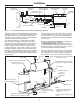
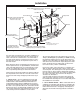
Refer to Fig. 1 for installation with commercial dish-
washer to provide hot water for sanitizing rinse. Note:
Adjust the pressure reducing valve to the dishwasher
manufacturer’s recommended pressure (usually between
15 and 25 psi) (103-172kPa), with water flowing to the
dishwasher.
2. THERMAL EXPANSION — Determine if a check valve
exists in the inlet water line. It may have been installed
in the cold water line as a separate back flow preventer,
or it may be part of a pressure reducing valve, water
meter or water softener. A check valve located in the
cold water inlet line can cause what is referred to as a
”closed water system”. A cold water inlet line with no
check valve or back flow prevention device is referred to
as an ”open” water system.
As water is heated, it expands in volume and creates
an increase in the pressure within the water system.
This action is referred to as ”thermal expansion”. In an
”open” water system, expanding water which exceeds
the capacity of the water heater flows back into the city
main where the pressure is easily dissipated.
A ”closed water system”, however, prevents the
expanding water from flowing back into the main supply
line, and the result of ”thermal expansion” can create
a rapid, and dangerous pressure increase in the water
heater and system piping. This rapid pressure increase
can quickly reach the safety setting of the relief valve,
causing it to operate during each heating cycle. Thermal
Installation
Introduction
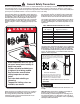
WA RNING
!
WA RNING
!