
Instructions / Assembly

4
expansion, and the resulting rapid, and repeated expan-
sion and contraction of components in the water heater
and piping system can cause premature failure of the
relief valve, and possibly the heater itself. Replacing the
relief valve will not correct the problem!
The suggested method of controlling thermal expan-
sion is to install an expansion tank in the cold water
line between the water heater and the check valve. The
expansion tank is designed with an air cushion built
in that compresses as the system pressure increases,
thereby relieving the over pressure condition and elimi-
nating the repeated operation of the relief valve. Other
methods of controlling thermal expansion are also avail-
able. Contact your installing contractor, water supplier,
or plumbing inspector for additional information regard-
ing this subject.
If a recirculation line is installed, the return connection
should be made to a tee close to the inlet connection
on the water heater. A check valve should always be
installed in the recirculation line to prevent cold water
from entering.
Factory designed Equa-Flow Manifolds, and jacketed,
insulated storage tanks are available.
3. WATER CONNECTIONS—This heater may be con-
nected individually in multiples with others, or with an
external hot water storage tank. It may also be used to
boost the temperature of preheated water.
Inlet and outlet water connections are clearly marked
next to the connections on the heater. Use only clean,
new galvanized steel, copper or approved plastic for
pipe for water connections. Local codes shall govern
Installation
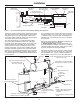
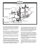
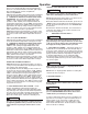
Figure 1. — Recommended installation for dishwashing sanitizing rinse application
Temperature /
Pressure Gauge
Dishwasher
Water Shock
Arrestor
Pressure Reducing
Valve with By-pass
High Temp
Limit Control
Thermostat(s)
Dial(s)
SYSTEM SENTINEL
Indicators
Shut-off
Valve
Water Inlet
Circulation Return Line
Check Valve
Relief Valve
Discharge Line
Open Drain
Legs
6” Air Gap (152mm)
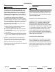
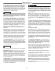
Figure 2. — Typical Gravity Circulating System
Temperature & Pressure Relief Valve
(Not visible in this view)
Refer to Local Codes
Storage Tank Temperature & Pressure Relief Valve
Refer to Local Codes
Temperature & Pressure Relief Valve
Discharge Pipe to suitable open drain
Temperature & Pressure Relief Valve(s)
Discharge Pipe(s) to suitable open drain
Branch Circuit from
Electrical Distribution Panel
Optional Return Outlet
Return Outlet
Cold Water Inlet
Shut-off Valve
Air Gap 6” (152mm)
Check Valve
Recirculation Loop
NOTES:
1.) Heater’s Outlet Piping must have
upward slope, otherwise use
Circulator.
2.) If vertical tank is used, follow same
layout.
2”
(51mm)
Storage Tank
Hot Outlet
Thermal
Expansion Tank
(If Required)
Vacuum Relief Valve
(If required by local codes)
Vacuum Relief Valve
(If required by local codes)