WARNING: If the information in these instructions is not followed exactly, a fire or explosion may result, causing death, personal injury, or property damage. For Your Safety! •D o not store or use gasoline or other flammable vapors and liquids in the vicinity of this or any other appliance. To do so may result in an explosion or fire. • Installation and service must be performed by a qualified installer, service agency, or the gas supplier.
CONTENTS Safety Important Safety Information Safety Precautions ��������������������������������������������������������������������� 2–8 Product Information Product Information ������������������������������������������������������������������������ 8 Specifications............................................................................
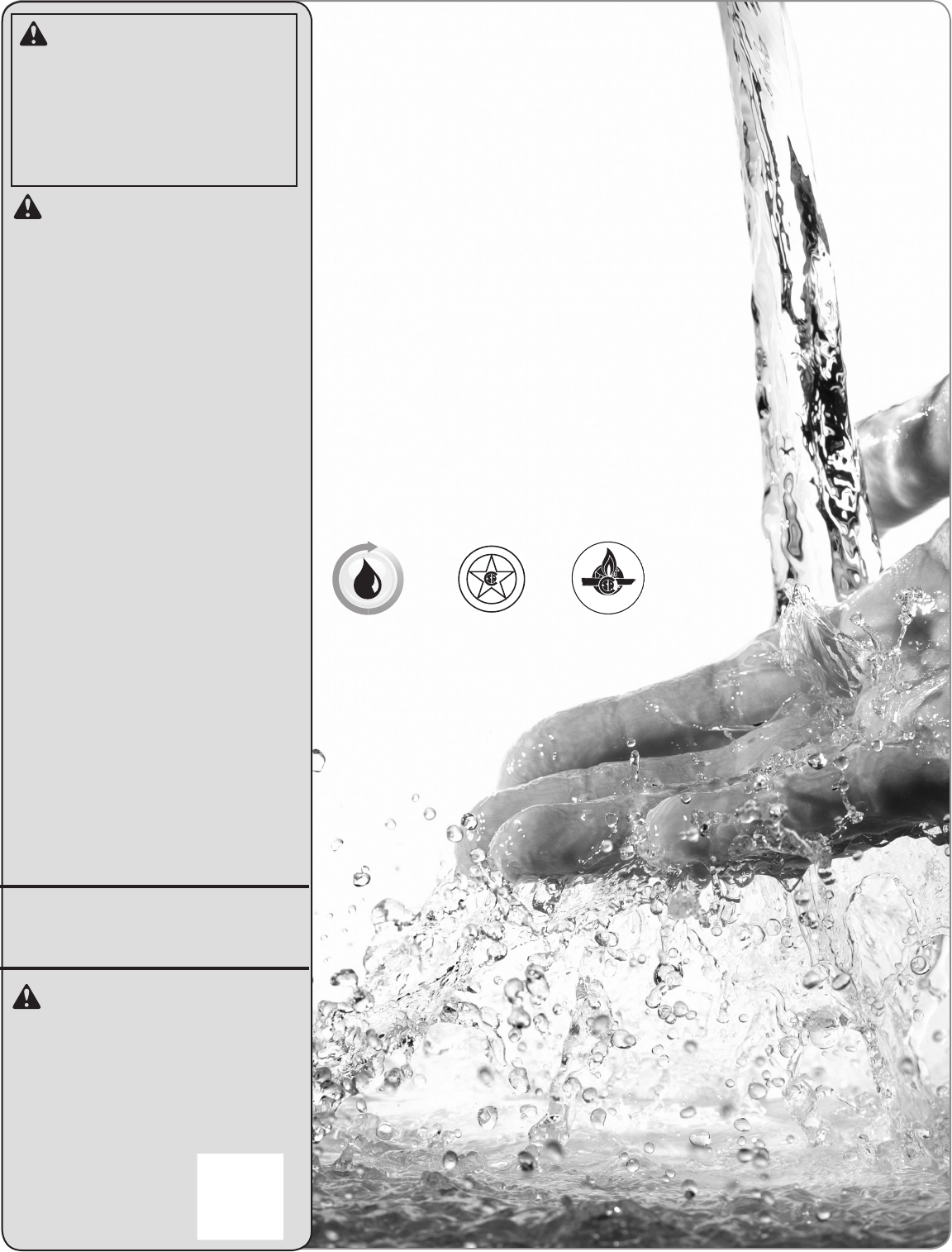
IMPORTANT SAFETY INFORMATION Water Heater Venting Safety DANGER: WARNINGS: • Gasoline and other flammable liquids, materials, and vapors (including paint thinners, solvents, and adhesives) are extremely dangerous. DO NOT handle, use, or store gasoline or other flammable or combustible materials anywhere in the vicinity of a water heater or any other appliance. Be sure to read and follow the labels on the water heater, as well as the warnings printed in this manual.
IMPORTANT SAFETY INFORMATION Water Supply Safety ! DANGERS: DANGER CAUTIONS: Safety • WATER TEMPERATURE SETTINGS • This water heater must only be used ! – Safety and energy conservation with the following water supply system are factors to be considered when conditions: selecting the water temperature –W ith clean, potable water free of corrosive setting of a water heater’s remote chemicals, sand, dirt, or other contaminants. control.
IMPORTANT SAFETY INFORMATION • N ever attempt to convert the water heater from natural gas to LP or vice versa. The water heater must only use the fuel type in accordance with listing on data plate— natural gas for natural gas units and LP for LP units. Any other fuel usage will result in death or serious personal injury from fire and/or explosion. This water heater is not certified for any other fuel type. • Both natural gas and propane (LP) have an odorant added to aid in detecting a gas leak.
IMPORTANT SAFETY INFORMATION Safety Before operating this water heater, be sure to read and follow the instructions on the label pictured below and all other labels on the water heater, as well as the warnings printed in this manual. Failure to do so can result in unsafe operation of the water heater, resulting in death, personal injury, or property damage. Should you have any problems reading or following the instructions in this manual, STOP and get help from a qualified service technician.
IMPORTANT SAFETY INFORMATION Electrical Safety WARNINGS: • F or your safety, the information in this manual must be followed to minimize the risk of fire, explosion, or electric shock that can result in death, personal injury, and/or property damage. • Field wiring connections and electrical grounding must comply with local codes or, in the absence of local codes, with the latest edition of the National Electrical Code, ANSI/NFPA 70, or in Canada, Canadian Electrical Code, CAN/CSA C22.1, Part 1.
IMPORTANT SAFETY INFORMATION Safety General Installation and Maintenance Safety SAFETY PRECAUTIONS: WARNINGS: Product Information • T his water heater must be installed in accordance with these instructions, local codes, utility company requirements and/or in the absence of local codes, use the latest edition of the American National Standard/National Fuel Gas Code (NFGC), ANSI Z223.1 and National Fire Protection Association, NFPA 54, or in Canada, CAN/CSA B149.
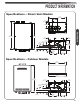
PRODUCT INFORMATION Specifications – Direct-Vent Models 5 /2" (140 mm) 1 3 3/8" (86 mm) 17 7/8" (454 mm) 6 1/4" (159 mm) Product Information 18 5/8" (473 mm) 29 1/4" (743 mm) 27 5/8" (702 mm) 2 1/4" (59 mm) 5 1/2" (140 mm) 41/8" (105 mm) 3 7/8" 2 7/8" (98 mm) (73 mm) 9 3/4" (248 mm) 11/2" (38 mm) 9 1/2" (241 mm) 2 1/8" (54 mm) 6 1/8" (156 mm) Specifications – Outdoor Models 17 7/8" (454 mm) 18 5/8" (473 mm) 27 5/8" (702 mm) 51/2" (140 mm) 21/4" (59 mm) 41/8" 3 7/8" (105 mm) 2 / " (98 mm) (7
PRODUCT INFORMATION Specifications English Rating Label The following product information can be found from the rating label on this water heater. Product Information A. Model Number B. Serial Number C. Data Bar Code D. Heater Type E. Installation Type F. Type of Gas G. Max. Inlet Gas Pressure H. Min. Inlet Gas Pressure J. Recovery Rating K. Max. BTU Input Rating L. Min. BTU Input Rating M. Manifold Gas Pressure N. Certification Stamp P. Alternate Approval Stamp Q.
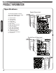
PRODUCT INFORMATION General Descriptions Typical Direct-Vent Water Heater (Shown Without Venting) Product Information Remote Control With Power Switch Water Filter Power Supply Cord Union To Hot Water Faucet(s) Manual Gas Shut-Off Valve (Supplied) Relief Relief Valve Valve Manual Gas Supply Line Shut-Off Valve Union Condensate Pipe* Service Valve Sediment Trap Cap Drain Valve To Suitable Drain Cold Water Supply Shut-Off Valve To Suitable Drain *Note: A flexible drain tube can be used 11
PRODUCT INFORMATION Typical Outdoor Water Heater (No Venting Required) This water heater is for OUTDOOR installation only. DANGER: DO NOT install this water heater indoors or in a confined space. It is designed for outdoor installation only. Any other type of installation will result in death or serious personal injury.
USING YOUR WATER HEATER Safety Precautions WARNING: • F lammable vapors can be drawn by air currents from surrounding areas to the water heater. Vapors can ignite causing death, personal injury, or product damage. • DO NOT store or use flammable or combustible materials (gasoline, paint thinner, adhesives, solvents, newspapers, rags, mops, etc.) in the vicinity of the water heater or any other gas appliance.
USING YOUR WATER HEATER Setting the Water Temperature (cont.) Maximum water temperature occurs while the water heater burner is ON. To determine the water temperature: Turn on the hot water faucet and place a thermometer in the water stream. NOTICE: The temperature set point on the standard remote control cannot be increased above 112°F (44°C) when a hot water faucet is in the open position. To achieve temperatures above 120°F (49°C) or 85°F (29°C), contact a qualified service technician.
CARING FOR YOUR WATER HEATER Water Heater Inspections Venting System (Direct Vent Only) The venting system should be inspected annually to ensure all of the vent sections are secure and airtight. Qualified service personnel are familiar with vent system inspections and may be contacted for advice. WARNING: DO NOT operate the water heater if the vent system shows signs of leaking exhaust. Leaking exhaust could lead to death, personal injury, and/or product failure.
CARING FOR YOUR WATER HEATER Water Heater Inspections (cont.) Burner It is recommended the burner be annually inspected by a qualified service technician. DANGER: Burner Sight Glass Shock Hazard – Removing the front cover panel exposes you to live electricity. Electric shock will cause death or serious personal injury. 3 While the water heater is operating, inspect the main burner flames through the burner sight glass. The flames should be blue when the main burner is firing.
CARING FOR YOUR WATER HEATER Care and Cleaning DANGER: Shock Hazard – Make certain power to the water heater is OFF before removing protective cover for any reason. Electric shock will cause death or serious personal injury. WARNING: Combustible materials, such as clothing, cleaning materials, or flammable liquids, must not be placed against or next to the water heater. Fire or explosion can occur causing death, personal injury, and/or product damage. NOTICE: The air intake requires a minimum of 12 in.
CARING FOR YOUR WATER HEATER Care and Cleaning (cont.) CAUTION: DO NOT tap or force the filter during removal. This can deform and/or damage the filter. 4 Unscrew the water filter from the base of the cold water inlet line and carefully slide it out of the line. 5 Care Instructions Clean the water filter under running water. To remove severe sediment and dirt, use a soft brush. 18 CAUTION: DO NOT overtighten the water filter. Overtightening can deform and/or damage the filter.
CARING FOR YOUR WATER HEATER Preventive Maintenance WARNING: Failure to perform routine preventive maintenance can prevent the water heater from operating properly. Improper operation can cause carbon monoxide dangers, excessive water temperatures, and other potentially hazardous conditions resulting in death, personal injury, and/or product damage. NOTICE: If the pressure relief valve on the hot water heater discharges periodically, this may indicate a problem in the water system.
CARING FOR YOUR WATER HEATER Draining the Water Heater WARNING: Failure to follow these draining instructions can cause serious personal injury from scalding and/or product damage. Cold Water Supply Shut-Off Valve 5 Close the water shut-off valve. Water Drain Valve Water Filter 1 Turn off the water heater by pressing the POWER ON/ OFF button on the remote control. 6 Water Drain Plug Find the water drain valve, the water filter and the water drain plug located at bottom of the water heater.
CARING FOR YOUR WATER HEATER CAUTION: Even when drained properly, a small amount of water will remain in the water heater. In cold weather conditions, this water can freeze. If this happens, allow the defrost protection on the water heater at least 30 minutes to melt the frozen water. The water heater will not work properly until this water is thawed. To put the water heater back in service: 4 Open all hot water faucets and let run until all air has been purged from the lines. Close all hot water faucets.
CARING FOR YOUR WATER HEATER Draining the Water Heater (cont.) Standard Drain Method Service isolator valve kits may be purchased from the manufacturer, distributor, or place of purchase. The kits include two full-port isolation valves to be used in the inlet and outlet water lines. These kits provide a means for full diagnostic testing and ease of system flushing and draining.
CARING FOR YOUR WATER HEATER Vacation and Extended Shutdown WARNING: Failure to drain the water heater can cause serious personal injury from scalding and/or product damage. The water heater and piping should be drained if they might be subjected to freezing temperatures. See “Freeze Protection” section on this Use and Care Manual. If the water heater is to remain idle for an extended period of time, the power and water to the heater should be turned off.
CARING FOR YOUR WATER HEATER Troubleshooting Chart (cont.) Problem Water not hot enough. Possible Cause Solution 1. The temperature may be set too low. 1. Increase the temperature setting at 2. The gas valve is not completely opened. 2. Check and completely open the gas valve. 3. Gas supply pressure is low. 3. Contact your gas utility company or gas 4. Bleed-over in one of the hot water 4. Contact a dealer or a qualified service 1. Temperature is set too high. 1.
CARING FOR YOUR WATER HEATER Service Error Code Chart Your water heater has an electronic diagnostic system built into it. When the water heater finds a problem, it displays an error code in the LED display on the remote control. The chart on the next page lists the error codes along with their possible problem and solution. Using this chart may help you diagnose and/or fix a problem you may be experiencing. Please refer to this chart before calling for service assistance.
CARING FOR YOUR WATER HEATER Service Error Code Chart (cont.) Error Code Possible Cause Solution Water heater has buildup of lime deposits. Contact a dealer or qualified service technician. Air intake or vent exhaust opening may be blocked. Remove any blockage. (Air intake requires 12 in. [30 cm] of clearance.) The vent pipes on the vent termination may not be connected properly. Contact a dealer or qualified service technician. The gas shut-off valve is not fully opened.
Installation INSTALLATION INSTRUCTIONS FOR THE CONTRACTOR 27
INSTALLATION INSTRUCTIONS General Standards Compliance This water heater must be installed in accordance with these instructions, local codes, and utility company requirements. In the United States where local codes are not available, use the latest edition of the American National Standard/National Fuel Gas Code. A copy of the Fuel Gas Code can be purchased from either the American Gas Association, 400 North Capitol Street Northwest, Washington, DC 20001, as ANSI standard Z223.
INSTALLATION INSTRUCTIONS 0" min. (0 mm) General Choosing a Location (cont.) 12" min. (300 mm) Sealing Plate 0" (0 mm) 12" min. (300 mm) 1/2" min. (13 mm) • Every vent or air intake pipe penetration of a floor or ceiling should be sealed. •F ailure to install and properly vent the water heater to the outdoors as outlined on "Venting" can result in unsafe operation. 12" min. (300 mm) • Minimum water heater clearances from combustible and noncombustible construction are as follows: – 1/2 in. (1.
INSTALLATION INSTRUCTIONS General Product Inspection Visually inspect the water heater for any possible damage. Verify that all included supplied parts are present as shown. Check the rating plate on the water heater to make sure the water heater was designed to be used with the supplied type of gas (natural or LP).
INSTALLATION INSTRUCTIONS General Water Heater Installation (cont.) NOTICE: The National Fuel Gas Code (NFGC) and CAN/CSA B149.1 mandate a manual gas shut-off valve. See NFGC/B149.1 for complete instructions. Local codes or plumbing authority requirements may vary from the instructions or diagrams provided and take precedence over these instructions.
INSTALLATION INSTRUCTIONS General Water Heater Installation (cont.) WARNING: Typical Installation of Outdoor Water Heater (No Venting Required) DO NOT install this water heater indoors or in a confined space. It is designed for outdoor installation only. Any other type of installation can result in death, personal injury, and/or damage to the product or property. This water heater is for OUTDOOR installation only.
INSTALLATION INSTRUCTIONS Mounting the Water Heater General CAUTION: Reinforcement of the wall is required where the wall is not strong enough to hold the water heater. Failure to do so could result in personal injury and/or property damage. The mounting location for the water heater should allow for easy access and operation. 3 Attach the mounting bracket to the wall and secure it by 4 screws and washers. Make sure it is level and that it can support the weight of the water heater.
INSTALLATION INSTRUCTIONS Venting for Direct-Vent Water Heater DANGER: Venting Failure to properly vent the water heater to the outdoors as outlined in this Venting section will result in death or serious personal injury. To avoid the risk of fire, explosion, or asphyxiation from carbon monoxide, NEVER operate the water heater unless it is properly vented and has adequate air supply for proper operation as outlined in this Venting section.
INSTALLATION INSTRUCTIONS Venting for Direct-Vent Water Heater Vent Lengths and DIPswitch Adjustments To have a longer vent length with 2" vent, A-2 setting is required: Venting Before starting the vent installation, careful planning should be given to the routing and termination of the vent pipes. The length of the vent pipes (inlet and outlet) should be kept to a minimum. Also, see pages 39–40 and 46 for vent terminal placement.
INSTALLATION INSTRUCTIONS Venting for Direct-Vent Water Heater Dip #2 is on 5 To set A-2 setting, change the second swtich on "DIP 2" to the ON position (UP). NOTICE: DO NOT alter any other DIP switch settings. Please contact technical service listed on page 26 of this use and care manual if you have any questions of DIP switch adjustments. The system will not operate if there is excessive restriction (pressure drop) in the venting system.
INSTALLATION INSTRUCTIONS Venting for Direct-Vent Water Heater Preexisting Venting Notes: The unit may be vented horizontally through a wall or vertically through the roof. Pipe runs must be adequately supported along both vertical and horizontal runs. Maximum unsupported span is recommended to be no more than 4 feet (1.2 m). It is imperative that the first hanger be located on the horizontal runs immediately adjacent to the first 90-degree elbow from the vertical rise.
INSTALLATION INSTRUCTIONS Venting for Direct-Vent Water Heater In the Commonwealth of Massachusetts Venting The Commonwealth of Massachusetts requires compliance with regulation 248 CMR 4.00 and 5.00 for installation of through-the-wall vented gas appliances as follows: 5.08: Modifications to NFPA–54, Chapter 10 (1) Revise NFPA–54 section 10.5.4.
INSTALLATION INSTRUCTIONS Venting for Direct-Vent Water Heater Inside corner detail Venting Fixed closed Operable V VENT TERMINAL X AIR SUPPLY INLET Fixed Operable closed AREA WHERE TERMINAL IS NOT PERMITTED Horizontal Vent Terminal Location for Other than Direct Vent The following information should be used for determining the proper location of the vent terminal for direct vent water heaters. Canadian Installations A= C learance above grade, veranda, porch, deck or balcony.
INSTALLATION INSTRUCTIONS Venting for Direct-Vent Water Heater Venting Inside corner detail Fixed Operable closed Fixed closed Operable Regulator vent outlet V VENT TERMINAL AREA WHERE TERMINAL IS NOT PERMITTED X AIR SUPPLY INLET Horizontal Vent Terminal Location for Direct Vent The following information should be used for determining the proper location of the vent terminal for direct vent water heaters.
INSTALLATION INSTRUCTIONS Horizontal Vent Considerations – DO NOT terminate vent directly on brick or masonry WARNING: surfaces. Use rust-resistant, sheet-metal backing plate behind the vent.
INSTALLATION INSTRUCTIONS Venting for Direct-Vent Water Heater (cont.) Wall Plate (recommended) Venting Exhaust Vent Pipe 12” (30 cm) Minimum Air Intake Pipe Upward Slope to Termination Inspection Access Panel (Optional) Ceiling Inspection Access Panel (Optional) Horizontal Vent Installation WARNING: Danger of fire or bodily injury – Solvent cements and primers are highly flammable. Provide adequate ventilation and DO NOT assemble near heat source or open flame. DO NOT smoke.
INSTALLATION INSTRUCTIONS Horizontal Vent Installation (cont.) Fasteners will vary depending on the wall type. F or particle board or composite sheathing, use 4 hollow wall anchors. The anchors should be at least 1/8 in. (0.3 cm) in diameter and the appropriate length for the sheathing thickness. F or masonry walls, use suitable masonry anchors long enough to pass through the wall.
INSTALLATION INSTRUCTIONS For information about termination kits, refer to "If You Need Service" on page 26, "Call for Assistance" for the telephone number to speak to a Customer Service Representative. Venting for Direct-Vent Water Heater (cont.) Alternative Horizontal Vent Installations Venting Alternative horizontal vent termination kits are commercially available. Please refer to the instruction sheet packaged with the kit for complete installation instructions.
INSTALLATION INSTRUCTIONS Vertical Vent Installation WARNING: Improper vent installation can result in death, personal injury, product damage, and/or poor performance. NOTICE: Free-standing vent pipe that penetrates a roof/ceiling requires another means of support from a second location. NOTICE: A, B Only Rheem-approved AND ULC S636 approved termination and parts must be used during installation.
INSTALLATION INSTRUCTIONS Venting for Direct-Vent Water Heater (cont.) Vertical Vent Terminal Location Venting Optional 12" Min. (300 mm) Air Intake Vent Pipe Through Roof A, B The following chart with diagrams details the minimum dimensional information needed to determine the proper location of the vertical vent terminal for direct-vent indoor tankless water heaters: Location U.S. Installation Requirements1 Canadian Installation Requirements2 A = Minimum clearance above the roof level. 12 in.
INSTALLATION INSTRUCTIONS Standard Vertical Vent Termination Optional Venting Adjustable Roof Flashing Support Clamp Upward Slope Support Hanger Air Intake Pipe Exhaust Vent Pipe To Suitable Drain 47
INSTALLATION INSTRUCTIONS Venting for Direct-Vent Water Heater (cont.) Alternative Vertical Vent Termination Alternative vertical vent termination kits are commercially available. Please refer to the instruction sheet packaged with the kit for complete installation instructions. WARNING: Venting Under no circumstances should the exhaust pipe and the air intake pipe be connected together.
INSTALLATION INSTRUCTIONS Water Quality Install a water treatment device or water softener at the same time as the original installation of the water heater. Rheem offers a water treatment accessory that can be installed with the water heater. (See below). Flush the water heater’s heat exchanger regularly. Rheem offers a flush kit and isolation valves to help remove scale build up. (See below) Plumbing Water quality must be taken into account when installing and maintaining the water heater.
INSTALLATION INSTRUCTIONS Thermal Expansion Plumbing Determine if a check valve exists in the inlet water line. Check with your local water utility company. It may have been installed in the cold water line as a separate back flow preventer, or it may be part of a pressure reducing valve, water meter or water softener. A check valve located in the cold water inlet line can cause what is referred to as a “closed” water system.
INSTALLATION INSTRUCTIONS Water Supply Installation NOTICE: • Use only Teflon tape on all COLD and HOT water connections. • If the water flow resistance of a showerhead is too high, the burner in the water heater will fail to ignite. Keep all showerheads clean from debris that could cause additional pressure drop. • If using mixing valves on the outlet, choose one that prevents COLD water pressure from overcoming HOT water pressure.
INSTALLATION INSTRUCTIONS Water Piping Arrangement With Service Valve Kit Service valve kits can attach to all tankless water heater systems. All kits include two full-port isolation valves to be used in the COLD and HOT water lines. When installed, these valves allow one person full diagnostic testing and ease of flushing the system. Contact your distributor or place of purchase for availability and installation information.
INSTALLATION INSTRUCTIONS Hot and Cold Pipe Insulation Installation WARNINGS: • When pipe insulation is not rated for the appropriate weather conditions, install electric heat tracing or equivalent to prevent freezing of the pipes. • DO NOT insulate or block drain valve on the hot outlet fitting. • If pipes are allowed to freeze, the water heater and the pipes may malfunction or leak due to freezing water.
INSTALLATION INSTRUCTIONS Gas Supply Gas Supply System Gas Piping WARNING: DO NOT attempt to convert this water heater for use with a different type of gas other than the type shown on the rating plate. Doing so could result in death, personal injury, explosion or fire, product damage, and/or poor operating conditions or performance.
INSTALLATION INSTRUCTIONS Gas Supply (cont.) Determining the required pipe size. Final Considerations The gas system is designed to operate at a certain maximum pressure drop. A pressure drop greater than what is permissible can cause operational issues with the gas appliances. The National Fuel Gas Code (NFPA 54, ANSI Z223.1 2012) allows for three pressure drop levels, a 0.3 inch W.C., (see table 2); a 0.5 inch W.C., (see table 3) and a 3.0 inch W.C., (see table 4) pressure drop for natural gas.
INSTALLATION INSTRUCTIONS Gas Supply (cont.) This is an example, in US, refer to current National Fuel Gas Code, NFPA 54 for correct pipe sizing chart, and in Canada, refer to current Natural Gas and Propane Installation Code CAN/CSA B149.1. Table 2 - Pipe-Sizing - Natural Gas Table 3 - Pipe-Sizing - Natural Gas Schedule 40 Metallic Pipe (Black Iron) Inlet System Pressure: Less than 2 PSI (55 inches W.C.) Allowable Pressure Drop: 0.3 inches W.C. Specific Gravity : 0.
INSTALLATION INSTRUCTIONS Gas Supply (cont.) Gas Supply Installation 1 Install the manual gas appliance shut-off valve to the gas connection at the water heater. The shut-off is supplied with the water heater. 4 Using the proper-size piping, fittings, and components, build the gas supply line to the water heater. NOTICE: 2 Install a ground joint union or ANSI design-certified semi-rigid or flexible gas appliance connector to the open end of the manual gas appliance shut-off valve. The NFGC, ANSI Z223.
INSTALLATION INSTRUCTIONS Leak Testing WARNING: Never use an open flame to test for gas leaks, because death, personal injury, and/or property damage can result. The water heater and its gas connections MUST be leaktested at normal operating pressures before the unit is placed in operation. These tests should also include all factory connections. Turn on the gas shut-off valve(s) to the water heater. • Use a soapy water solution to test for leaks at all the connections and fittings.
INSTALLATION INSTRUCTIONS Gas Supply (cont.) High-Altitude Installation The water heater is certified for installations up to 2000 ft. (610 m) above sea level. The input rating of this water heater is based on sea level operation. At higher elevations, the actual input rate may be lower than the value listed on the rating label due to the derating of Natural Gas and LP Gas. NOTICE: For installations above 2000 ft.
INSTALLATION INSTRUCTIONS Electrical Wiring Diagram 60
INSTALLATION INSTRUCTIONS Electrical Wiring (cont.) Remote Control Selection and Location WARNING: Field wiring connections and electrical grounding must comply with local codes or, in the absence of local codes, with the latest edition of the National Electrical Code, ANSI/ NFPA 70, or in Canada, Canadian Electrical Code, CAN/CSA C22.1, Part 1. NOTICE: The provided remote control will allow maximum temperature settings of 120°F (49°C).
INSTALLATION INSTRUCTIONS Remote Control Installation WARNING: Field wiring connections and electrical grounding must comply with local codes or, in the absence of local codes, with the latest edition of the National Electrical Code, ANSI/ NFPA 70, or in Canada, Canadian Electrical Code, CAN/CSA C22.1, Part 1. NOTICE: Remote control cable needs to be type CL3R/CMR shielded security wire equivalent (18 AWG) and need not to be polarity-sensitive. It is not recommended to have wiring exposed.
INSTALLATION INSTRUCTIONS Electrical Wiring (cont.) Connecting the Remote Control to the Water Heater: 4 1 Firmly tighten the terminal screws by hand. Ensure that the power to the water heater has been disconnected. Remote Control Connection Cover 2 Loosen the one screw located on the remote control connection cover. The connection cover is made of white plastic. 5 Secure the remote control extension cable on the hook located on the side of the remote control connection base.
INSTALLATION INSTRUCTIONS Insulation Blankets In general, insulation blankets for external use on gas water heaters are not necessary. The purpose of an insulation blanket is to reduce the standby heat loss from the water heater’s storage tank. Since these water heaters DO NOT store water, they eliminate the need for the insulation blanket. ! WARNING: Never cover the air inlet, flue outlet, or operating and warning labels attached to the water heater.
INSTALLATION INSTRUCTIONS Installation Checklist A. Water Heater Location C. Water Supply/Relief Valve Indoor water heaters must be installed indoors. Water supply has sufficient pressure. Outdoor water heaters must be installed outdoors. Air has been purged from the water heater and the piping. Close to area of ventilation termination (indoor models). Water connections tight and free from leaks. Protected from freezing temperatures. Water filter is clean and in place.
INSTALLATION INSTRUCTIONS Piping for Space Heaters If this water heater is installed in an application intended to supply domestic hot water needs and hot water for space heating purposes, DO NOT connect the heater to an existing heating unit or components of a heating system that have previously been used with a nondrinking water system. Local codes or plumbing authority requirements may vary from the instructions or diagrams provided in this manual and take precedence over these instructions.
INSTALLATION INSTRUCTIONS Recirculation Control Pump Requirements Local codes or plumbing authority requirements may vary from the instructions or diagrams provided in this manual and take precedence over these instructions. Voltage: 120V, 60Hz In-rush current: Less than 2.5 amps Amperage: less than 2.0 amps Your tankless water heater has the ability to control an external recirculation pump.
INSTALLATION INSTRUCTIONS Recirculation Control (cont.) Installation Control Board Blue connector BK Add 4 Amp Fuse PUMP 1 W Disconnect all electric power to the water heater. Cut blue connector and splice wires. 5 To connect to the pump, cut the blue connector, splice the wires, and add a 4 amp fuse to the hot wire of the pump. Rheem recirculation pump kit includes a molex connector and a 4 amp fuse so splicing wires is not required. 2 Remove the front cover panel on the water heater.
INSTALLATION INSTRUCTIONS Recirculation Control (cont.) Turn On the remote control. The pump and water heater will turn on to raise recirculation loop temperature. Recirculation Operation As set from factory 8 MIN MAX ADJ The factory setting for this switch should all be in the OFF position (DOWN). The water heater is turned ON when the recirculation pump starts operation. The water heater produces hot water at the setting temperature.
INSTALLATION INSTRUCTIONS Activating the Water Heater WARNING: Before operating this water heater, be sure to read and follow the instructions on the following label, all labels on the water heater, and the “Important Safety Information” section in this manual. Failure to do so can result in unsafe operating conditions that can result in death, personal injury, property damage, and/or product damage.
INSTALLATION INSTRUCTIONS Activating the Water Heater Operating Instructions Read, understand, and follow the safety information listed on the operating label and in the “Important Safety Information” section in this manual. 4 Turn on all electric power to the water heater. The water heater burner will automatically light when there is a demand for hot water. WARNING: 1 Disconnect all electric power to the water heater. DO NOT attempt to light the burner by hand.
INSTALLATION INSTRUCTIONS The contents on pages 72 through 80 should only be performed by qualified service personnel. Setting the Water Temperature WARNING: Improper adjustment, alteration, service, or maintenance can result in death, personal injury, property damage, and/ or product damage. Maximum Temperature Adjustment by the Main Remote Control (UMC– 117) DANGER: Water temperatures above 125°F (52°C) will result in death and/or severe burns from scalding.
INSTALLATION INSTRUCTIONS Setting the Water Temperature (cont.) 4 While “140” is blinking, press the UP and DOWN adjustment buttons at the same time. “140” will appear without blinking. 5 Press the UP or DOWN adjustment button to set the desired temperature. 3 Press the DOWN adjustment button repeatedly until 100°F (38°C) or 85°F (29°C) shows in the LED display. Hold the DOWN button until the number on the display starts to blink.
INSTALLATION INSTRUCTIONS Setting the Water Temperature (cont.) Minimum Temperature Adjustment by the Main Remote Control (UMC– 117, USC1–117, and USC2–117) Residential water heater temperatures can be adjusted down to 85°F (29°C), when required. To change the temperature settings down to 85°F (29°C): 3 Press the DOWN adjustment button repeatedly until 100°F (38°C) shows in the LED display. NOTICE: LED display only shows °F. 1 Turn on the remote control.
INSTALLATION INSTRUCTIONS High-Altitude DIP Switch Adjustments (cont.) 6 If your vent lenth is relatively longer, B-2 setting is required. Change, the second switch on "DIP 2" to the ON position (UP). 2 Remove the front cover panel on the water heater. 7 If altitude is above 5,400 ft. (1650 m) and below 8,500 ft. (2590), change the fourth switch to the ON position (UP). C-1 setting completes. Dip Switches 3 Control Board Find DIP Switch 2 located in the top-right portion of the control board.
INSTALLATION INSTRUCTIONS High-Altitude DIP Switch Adjustments (cont.) WARNING: 10 Turn on the gas and water to the water heater by opening the shut-off valves. Minimum / Maximum vent lengths at B-1, B-2, C-1 and C-2 setting are as follows: Minimum Vent Length (intake/outlet) each at B-1 and C-1 Setting Number of 90° Elbows Maximum Length of 2" or 3" Straight Pipe 1 1.0 ft (0.
INSTALLATION INSTRUCTIONS Water Saving Control Water saving control is optional and is inactive as default. To activate this control, appropriate procedures must be followed. Water saving control can reduce waste water at initiation of hot water demand by reducing flow until outlet hot water reaches set temperature. It is recommended to turn ON this control if the water heater is installed in a drought area or anywhere water conservation is needed. Follow the steps below to turn ON the water saving control.
INSTALLATION INSTRUCTIONS Water Saving Control (cont.) 2 Remove the front cover panel on the water heater. Dip Switches 3 Control Board Find DIP Switch 1 located in the top-right portion at the control board. The switch labeled “DIP 1” is the top switch. 4 Change the third switch on “DIP 1” to the OFF position (DOWN). 5 Start/Adjust Turn on the gas and water to the water heater by opening the shut-off valves.
INSTALLATION INSTRUCTIONS Maintenance Notice Maintenance notice is an optional control and is inactive as default. Maintenance notice reminds users of water heater maintenance activities such as flushing the heat exchanger or replacing the water treatment filter (if applicable) in order to maximize the life of your tankless water heater. Contact technical service department listed on page 26 of this use and care manual if you are not familiar with these maintenance activities.
INSTALLATION INSTRUCTIONS Maintenance Notice (cont.) 11 Turn on the gas and water to the water heater by opening the shut off valves. 9 Replace the front cover panel. 10 Turn on the remote control. Error Code 88 Clearing When a tankless water heater has a certain number of hours of combustion, error code “88” is shown on the remote control.
PARTS REPLACEMENT Parts Ordering WARNING: 1. The model and serial number of the water heater from the rating plate. For your safety, DO NOT attempt to disassemble, repair, or replace any portion of this unit. Refer all repairs, service, and/or adjustments to qualified service personnel. Address all parts orders to the distributor or store where the water heater was purchased. All parts orders should include: 2. Specify the gas type (natural or LP) as marked on the rating plate. 3.
PARTS REPLACEMENT Parts Ordering (cont.
LIMITED WARRANTY For the RHEEM®, RUUD®, Richmond®, Paloma®, and EcoSmart® Residential Tankless Gas Water Heaters. GENERAL This Limited Warranty is only available to the original owner of the water heater at the original installation location. This Limited Warranty is not transferable. Rheem Sales Company, Inc.
LABOR, SHIPPING, AND PROCESSING COSTS For one (1) year after the Effective Date, Rheem will cover reasonable labor costs necessary to repair or replace a tankless water heater or component part that Rheem determines to be defective and covered by this Limited Warranty. The warranty service must be performed by a contractor that is licensed, state qualified, and trained to install and service Rheem's tankless water heaters.