
Instructions / Assembly

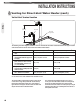


46
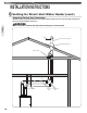
Venting
INSTALLATION INSTRUCTIONS
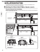
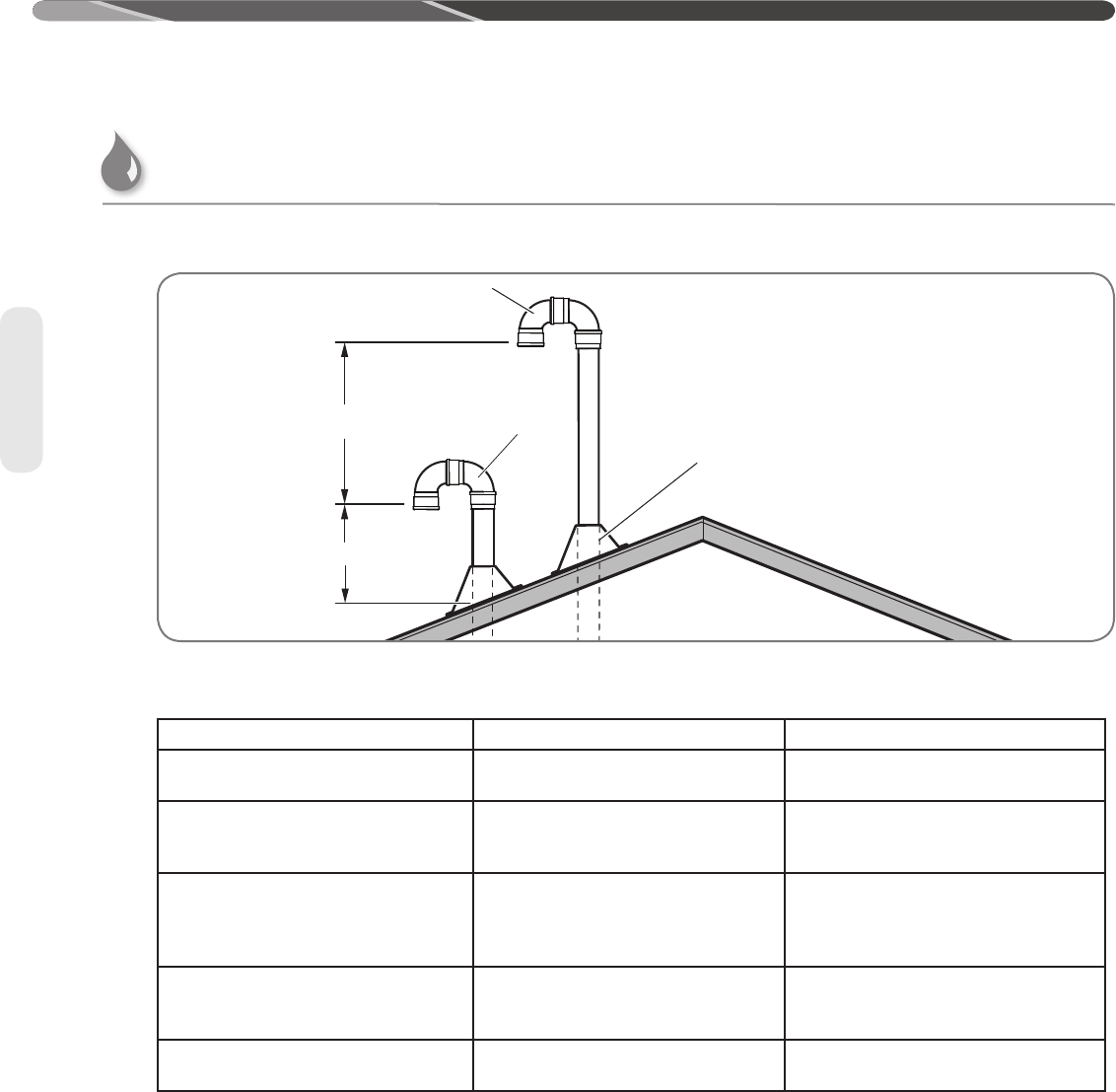
Vertical Vent Terminal Location
A, B
12" Min.
(300 mm)
Vent Pipe
Through Roof
Optional
Air Intake
The following chart with diagrams details the minimum dimensional information needed to determine the proper location
of the vertical vent terminal for direct-vent indoor tankless water heaters:
Location U.S. Installation Requirements
1
Canadian Installation Requirements
2
A = Minimum clearance above the roof
level.
12 in. (30 cm) above roof level.
18 in. (45.7 cm) above roof level.
B = Maximum clearance above roof
level (without additional support for
vent pipe).
24 in. (61 cm) above roof level.
24 in. (61 cm) above roof level.
C = Required vent clearance from any
gable, dormer, or other roof struc-
ture with building interior access
(i.e., vent, window).
4 ft. (1.2 m)
4 ft. (1.2 m)
D = Required vent clearance from any
forced air inlet, including dryer and
furnace air inlets.
10 ft. (3 m)
6 ft. (1.8 m)
E = Minimum/maximum horizontal dis-
tance between vent terminals
5.5 in. (14 cm)/24 in. (61 cm)
5.5 in. (14 cm)/24 in. (61 cm)
1 In accordance with current ANSI Z223.1/NFPA 54 National Fuel Gas Code.
2 In accordance with current CAN/CSA B149.1 Installation Codes.
The vertical intake air termination requires a return bend
or two short or long sweep radius 90° elbows to keep
the inlet downward and prevent entry of rain. Refer to
figure above for the proper location of the air intake with
respect to the exhaust outlet termination.
The vertical exhaust outlet termination is a 2-inch or
3-inch pipe which terminates at least 12 inches (30 cm)
above the air intake termination. The exhaust outlet
terminations must be at least 12 inches (30 cm) in US [at
least 18 inches (46 cm) in Canada] above the roof line or
anticipated snow levels.
Venting for Direct-Vent Water Heater (cont.)