
Use and Care Manual

50
Plumbing
INSTALLATION INSTRUCTIONS
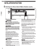
Water Supply Connections
CAUTION:
IMPORTANT—DO NOT apply heat to the HOT or COLD water
connections. If sweat connections are used, sweat tubing
to the adapter before fitting the adapter to the water
connections on the water heater. Any heat applied to the
water supply fittings will permanently damage the internal
components of the water heater.
NOTICE:
In cold environments, ice can accumulate in the water
heater’s connectors. Plug in the water heater power
cord for approximately 10 minutes before making these
connections. This will melt any ice buildup.
Plumbing should be carried out by a qualified plumbing
contractor in accordance with local codes.
Only use approved plumbing materials.
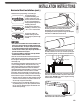
To allow the full flow capacity, it is recommended to
keep water inlet and outlet pipes 3/4" (1.9 cm) diameter
or larger.
To conserve energy and to prevent freezing, insulate
both COLD and HOT water supply lines. DO NOT
insulate the drain line or pressure-relief valve.
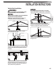
Recirculation
Direct recirculation is allowed, provided the loop is
thermostatically controlled, and a timer is used to
turn the pump off during off peak periods. The pump
must be sized for a minimum of 5 gpm at 25 ft of head
plus building head. A 10°F difference between the loop
thermostat setting and water heater temperature setting
must be maintained.
To ensure proper operation of the water heater, follow
these water pressure guidelines.
Operation of the water heater requires a minimum water
pressure of 14 psi (97 kPa) and a minimum water flow
rate of 0.4 gpm (1.5 lpm).
Water pressure of 40 psi (276 kPa) is required to achieve
maximum flow rate.
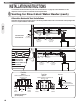
To maintain proper performance, there must be sufficient
water supply pressure.Required Water Pressure =
Min. Operating Water Pressure (14 psi [97 kPa])
+ Pipe Pressure Loss
+ Faucet Pressure Loss
+ Safety Margin (more than 5 psi [34 kPa]).
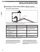
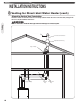
To supply HOT water to upper floors, additional water
pressure will be required (0.44 psi [3 kPa] per foot of
height). Calculate the distance between the water inlet of
the water heater (ground level) to the HOT water faucet
farthest away from the water heater (upper floor level).
Well water systems should be set to ensure a minimum
system pressure of 40 psi (276 kPa). The pressure
should remain constant and stable during the operation
of the water heater.
Gravity water pressure is not recommended. When the
water is supplied from a water supply tank, the height
of the tank, the diameter of the supply pipes, and
their relation to water pressure need to be taken into
consideration.
Thermal Expansion
Determine if a check valve exists in the inlet water line.
Check with your local water utility company. It may have
been installed in the cold water line as a separate back
flow preventer, or it may be part of a pressure reducing
valve, water meter or water softener. A check valve
located in the cold water inlet line can cause what is
referred to as a “closed” water system. A cold water inlet
line with no check valve or back flow prevention device
is referred to as an “open” water system. As water is
heated, it expands in volume and creates an increase
in the pressure within the water system. This action is
referred to as “thermal expansion”. In an “open” water
system, expanding water and the resulting pressure
increase which exceeds the capacity of the water heater,
flows back into the city main where the pressure is easily
dissipated.
A “closed” water system, however, prevents the
expanding water from flowing back into the main
supply line, and the result of “thermal expansion” can
create a rapid and dangerous pressure increase in the
water heater and system piping. This rapid pressure
increase can quickly reach the safety setting of the relief
valve, causing it to operate during each heating cycle.
Thermal expansion, and the resulting rapid and repeated
expansion and contraction of components in the water
heater and piping system can cause premature failure of
the relief valve, and possibility the heater itself.
NOTICE:
Replacing the relief valve will not correct the problem!
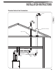
The suggested method of controlling thermal expansion
is to install an expansion tank in the cold water line
between the water heater and the check valve.
The expansion tank is designed with a built-in air
cushion that compresses as the system pressure
increases. This relieves the over-pressure condition and
eliminates the repeat operation of the relief valve. For
other approved methods of thermal expansion, contact
an installing contractor, water supplier, or plumbing
inspector.