
Instructions / Assembly


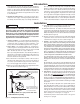


2. TEMPERATURE SETTINGS — The thermostat is adjusted
to its lowest temperature position when shipped from the factory.
To meet commercial water use needs, it is adjustable up to 180°F
(82°C). However, water temperatures over 125°F (52°C) can cause
severe burns instantly or death from scalds. This is the preferred
starting point for setting the control for supplying general purpose
hot water.
Safety and energy conservation are factors to be considered when
setting the water temperature on the thermostat. The most energy
efficient operation will result when the temperature setting is the
lowest that satisfies the needs consistent with the application.
Hotter water increases the Potential for Hot Water SCALDS.
When this water heater is supplying general purpose hot water
requirements for individuals, a thermostatically controlled mixing
valve for reducing point of use water temperature is recommend-
ed. Contact a licensed plumber or the local plumbing authority for
further information.
Outlet water temperature will vary during normal operating cycles.
Reliable temperature readings should be taken shortly after main
burner cycles off during a period of little or no use.
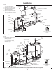
3. GAS MANIFOLD PRESSURE — With the gas valve supplied
with this water heater, main burner ignition occurs at a low or step
manifold pressure, which will then automatically build up to its
normal operating level . On the Power Assist Burner and Xtreme
units, ignition and manifold pressure occur immediately. The rated
operating manifold pressure is listed on the water heater rating
plate. For purposes of input adjustment, the minimum inlet gas
pressure(with main burner on) is also shown on the rating plate.
A 1/8” NPT tapping is provided on the outlet side of the gas valve
for connecting a manometer to check this pressure. If necessary,
adjust the pressure to the proper value by turning regulator adjust-
ment screw clockwise to increase pressure or counterclockwise to
decrease pressure.
4. CHECKINPUT — Consult the local Gas Company to determine the
heating value of the gas supplied. Check input by clocking gas meter with
all other gas appliances turned off. Use the following formula:
DO NOT exceed Input shown on the water heater's rating plate!
To insure accuracy for rating, clock enough cubic feet of gas so
that the clocked time is at least 60 seconds.
10
Operation
A. Do turn off manual gas shut-off valve if water heater has been sub-
jected to over heating, fire, flood, physical damage or if gas supply
fails to shut off.
B. Do Not turn on water heater unless it is filled with water.
C. Do Not turn on water heater if cold water supply shut-off valve is
closed.
D. Do Not store or use gasoline or other flammable vapors and
liquids, such as adhesives or paint thinner, in vicinity of this or any
other appliance. If such flammables must be used, open doors and
windows for ventilation, and all gas burning appliances in vicinity
should be shut off, including their pilot lights, to avoid vapors ignit-
ing.
NOTE: Flammable vapors may be drawn by air cur-
rents from surrounding areas to the water heater.
E. Do not allow combustible materials such as newspaper, rags or
mops to accumulate near water heater.
F. If there is any difficulty in understanding or following the OPERA-
TION or MAINTENANCE instructions, it is recommended that a
qualified person or serviceman perform the work.
Hydrogen gas can be produced in a hot water system served by
this water heater that has not been used for a long period of time
(generally two weeks or more). HYDROGEN GAS IS EXTREMELY
FLAMMABLE!! To dissipate such gas and to reduce risk of injury,
it is recommended that the hot water faucet be opened for sev-
eral minutes at the kitchen sink before using any electrical appli-
ance connected to the hot water system. If hydrogen is present,
there will probably be an unusual sound such as air escaping
through the pipe as the water begins to flow. Do not smoke or
use an open flame near the faucet at the time it is open.
SAFETY PRECAUTIONS
CAUTION
!
INPUT (btu/h) =
(3,600) x (Heating Value) x (Number of Cubic Feet Timed)
Seconds Clocked
DANGER
!
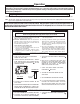
Figure 6. — Thermostat adjustment
120
140
°
F
1
8
0
1
6
0
1
4
0
1
3
0
1
2
0
1
1
0
1
0
0
THERMOST AT
°
C
8
0
7
0
6
0
5
0
4
0
To adjust the water temperature, insert a small straight
screwdriver into slotted screw in hole in front of
thermostat and turn wheel to desired setting. Ther-
mostat is adjustable up to 180º F.
CAUTION!! - Hotter water increases the risk of SCALDING!
White-Rodgers
Honeywell
WARNING
!
WARNING
!