
Instructions / Assembly


The manufacturer’s warranty does not cover any damage or defect
caused by installation, or attachment, or use of any special attach-
ment such as energy saving devices (other than those authorized
by the manufacturer) into, onto, or in conjunction with the water
heater. The use of such unauthorized devices may shorten the life
of the water heater and may endanger life and property. The manu-
facturer disclaims any responsibility for such loss or injury result-
ing from the use of such unauthorized devices.
1. INSPECT SHIPMENT — for possible damage. The manufacturer’s
responsibility ceases upon delivery of goods to the carrier in good
condition. Any claims for damage, shortage in shipments, or non
delivery must be filed immediately against carrier by consignee.
2. DRAFT HOOD — The combination draft hood - flue damper as-
sembly designed for and shipped with this water heater must be
installed, without alteration, directly on the flue outlet collar. DO
NOT substitute any other size or type of draft hood.
Before proceeding with installation, verify that the part number on
the draft hood - flue damper assembly matches that called for on
label near connector. If not, see your distributor or the store from
where the water heater was purchased.
A.) Place the draft hood - flue damper assembly on the flue outlet of
the water heater with the drive motor to the left front. Rotate as
necessary to position where the plug on the end of the wire har-
ness can freely engage in the receptacle of the drive motor.
B.) Mark a spot on top pan through the hole in support bracket at the
rear of the drive motor. (Refer to Figure 3.)
C.) Remove the draft hood - flue damper assembly and drill a hole
through the spot for securing it with sheet metal screw.
D.) Reinstall the draft hood - flue damper assembly and secure it with
a sheet metal screw through the support bracket. Also install three
(3) 3/8”(.95 cm) maximum length self drilling screws (supplied with
Damper Assembly) into holes located around the base of Damper
Assembly. (Refer to Figure 3.)
E.) Electrical connections to the drive motor are made with a plug that
is polarized to insure correct insertion. The drive motor receptacle
is external to the casing for easy access. (Refer to Figure 3.)
3. VENTING — The responsibility for providing a vent of adequate capacity
and in good usable condition is that of the installing contractor. If the water
heater is being installed as a replacement for an existing water heater, a
thorough inspection of the existing venting system must be performed prior
to any installation work. Verify that the correct materials and clearances
have been used for the installation. There is a limit to the Btu/h capacity of
any given vent or chimney style and height. For installations in the United
States, capacity tables are printed in Appendix “G” of the National Fuel
Gas Code (ANSI Z223.1). For installations in Canada, this information is
contained in Appendix B of CAN/CGA B-149.1Installation Codes
As an alternate method for sizing a vent connected to more than one
appliance, the effective area of the vent shall be not less than the area of
the largest vent connector plus 50% of the areas of additional draft hood
outlets.
Any horizontal run of vent connector connecting the draft hood to the
gas vent or chimney, must have an upward slope of at least 1/4” per foot
of length. Single wall vent connectors must be at least 6” from adjacent
unprotected combustible surfaces. Joints of vent connectors should be
securely fastened by sheet metal screws or other approved method. Pro-
vide support for vent, or vent connectors to keep weight off draft hood.
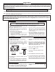
4. GAS SERVICE — The inlet gas pressure to the water heater must not
exceed 10.5” w.c. (2.6 kPa) for Natural gas and 13.0” w.c. (3.2 kPa) for
L.P. gas. Note: The Power Assist Burner Unit uses only Natural Gas and
should follow the guidelines stated in the previous sentence for inlet gas
pressure. For purposes of input adjustment, the minimum inlet gas pres-
sure (with main burner on) is shown on the rating plate. Check to see if
high or low gas pressure is present and then contact the gas company
for correction.
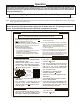
The gas line should be of adequate size to prevent undue pressure
drop. Sizing based upon Table 1 (on pg. 14) is recommended. No
additional allowance is necessary for an ordinary number of fittings.
A ground joint union and manual shutoff valve should be installed
in the gas line near the water heater so that the burner assembly
may be easily removed. The shut-off valve must be readily acces-
sible for turning on or off. See Fig. 4 or 5 on page 6.
A sediment trap must be installed at the bottom of the gas line.
See Fig. 4 or 5 on page 6.
5
Large exhaust fans can lower the air pressure inside a building or
room and interfere with proper venting and operation. Commercial
kitchens or other locations that must maintain a high flow of ex-
haust air should have the water heater installed in a separate room
with combustion and ventilation air supplied directly from outside
as described above.
F. CORROSIVE ATMOSPHERES — The heater should not be in-
stalled near an air supply containing halogenated hydrocarbons.
For example, the air in beauty shops, dry cleaning establishments,
photo processing labs, and storage areas for liquid and powdered
bleaches or swim pool chemicals often contain such hydrocarbons.
The air there may be safe to breathe, but when it passes through
a gas flame, corrosive elements are released that will shorten the
life of any gas burning appliance. Propellants from common spray
cans or gas leaks from refrigeration equipment are highly corrosive
after passing through a flame. The limited warranty is voided when
failure of water heater is due to a corrosive atmosphere. (Reference
is made to the limited warranty for complete terms and conditions.)
Introduction
Installation
WARNING
!
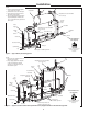
Figure 3. — Installing Damper / Draft Hood Assembly
Damper Mounting
Screw
3/8” Maximum Length Damper
Mounting Screw
Additional screws located at 90°
intervals around Damper Base
Insert Polarized Plug into re-
ceptacle on Drive Motor after
Damper / Draft Hood Assembly
is secured to water heater.
Note: Damper MUST be in open position when water
heater main burner is operating