
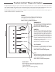
Instructions / Assembly

YES
CAUTION
!
Label all wires prior to disconnection when servicing controls. Wiring errors can cause improper and dangerous operation. VERIFY PROPER OPERATION AFTER SERVICING!
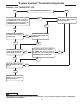
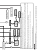
Section 3... the “IGNITION” LED
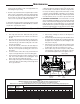
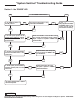
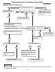
“System Sentinel” Troubleshooting Guide
Did the Damper Assembly
fully open?
Check Damper for obstruc-
tions—remove if necessary.
Did Damper fully open?
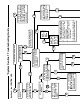
1. Remove Ignition Cable and check for
good continuity, replace if necessary.
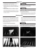
2. Check Ignitor Electrode gap for
proper spacing (1/8” to 5/32”).
Correct if necessary.
3. Examine Ceramic Insulator on Pilot
Assembly for cracks. Replace if
cracks are evident.
If all of the above components check
okay, replace Ignition Control Module.
Is 24 VAC present between the
Gray ground wire and the Red 24 V
wire connected to the Ignition
Control Module?
Check continuity of Red
and Gray wires between
Damper Assembly and
Ignition Control Module. Is
continuity “good”?
Remove Damper Drive
Motor cover; is the green
“CALL FOR HEAT” LED illu-
minated?
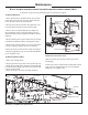
Damper Assembly is defective and must be replaced. The water heater may still be used until a replacement Damper Assembly can be installed by following these steps:
Turn off power to the water heater at the main power switch located on the side of the control enclosure. Order a replacement Damper Assembly.
Honeywell Damper: With power still off, remove Damper Drive Motor cover and move the Service Switch located to the right of the motor from th “NORMAL” position to the “SERVICE
position. Using a standard flat screwdrive, rotate the slotted white knob, located below the motor, counter-clockwise until the damper blade is in the open (fully vertical) position. Replace
cover.
Effikal Damper: With power still off, move the Service Switch located on the left side of the control enclosure from the “NORMAL” position to the “SERVICE” position. With pliers secured
on the damper shaft near the controller, rotate the damper counter-clockwise until the damper is in the fully open (fully vertical) position.
All Dampers: Turn power on at the main power switch located on the side of the control enclosure. The heater should now attempt its firing sequence.
* Denotes these boxes are for use with the “Power Assist Burner & Xtreme models” only.
Is Spark Ignitor operating?
(Can sparking be heard?)
The System Sentinel Panel is
defective and must be replaced.
Repair or replace the Wiring
Harness
Refer to Troubleshooting
Guide, Section 2...the “THER-
MOSTAT” LED to determine if
Thermostat is operable. Repair
or replace if required.
Ignition Control Module is defec-
tive and must be replaced.
The Thermostat has called for
heat, the Damper Assembly has
fully opened, and 24 VAC power is
being supplied to the Ignition
Control Module and the ignition
sequence will begin.
YES
YES
YES
YES
YES
NO
NO
NO
NO
NO
NO
NO
Is the “IGNITION” LED Illuminated?
Is the green “IGN GAS
PWR” LED illuminated?
*Is 24 VAC present
across coil of relay?
*Relay is defective and
must be replaced.
*Blower is defective
and must be replaced.
*Relay is defective and
must be replaced.
*Pressure switch is
defective and must be
replaced.
* P r e s s u r e
switch is
defective and
must be
replaced.
*Is there continuity
across normally
closed pole and
common pole of
pressure switch?
*Is there 120 VAC
across Brown wire
and Blue wire of
blower?
*Is there 24 VAC
present between
the common pole
and the normally
open pole of the
pressure switch?
*Is 24 VAC present between
terminal 6 and Gray ground
wire?
Is the damper marked
EFFIKAL?
NO
*NO
NO
YES
NO
YES
Is 24 VAC power present
between the Blue and Gray
wires in the Polarized Plug at
Damper Assembly?
YES
*Is blower operating?
YES
*NO
*YES
*NO
*YES
*NO
*NO
*YES
*YES
*YES
YES
*YES
*YES
NO