
Instructions / Assembly


6
Installation
SYSTEM SENTINEL
POWER
THERMOSTAT
IGNITION
PILOT VALVE
MAIN VALVE
ECO
®
SYSTEM SENTINEL
POWER
THERMOSTAT
IGNITION
PILOT VALVE
MAIN VALVE
ECO
®
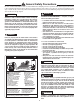
Figure 4. — Typical Gravity Circulating System
Hot Outlet
2"
Check Valve
Check Valve
Recirculation Loop
Storage Tank
Optional
Return
Outlet
Cold Water
Inlet
Shut-Off
Valve
Discharge Pipe to Suitable Open Drain
Discharge Pipe to Suitable Open Drain
Air Gap 6"
Gas Valve
Cap
Sediment Trap
Ground Joint Union
Thermostat
To Gas
Supply
Manual
Gas
Shut-Off
Temperature & Pressure Relief Valve
(See Local Code)
Temperature & Pressure Relief Valve
(See Local Code)
Temperature & Pressure Relief Valve
(See Local Code)
Discharge Line
to Suitable Open Drain
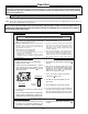
Temperature & Pressure
Relief Valve
Cold
Inlet
Shut-Off
Valve
Recirculation Loop
Recirculator
To
Gas
Supply
Manual
Gas
Shut-Off
Ground Joint Union
Thermostat
Manifolds
Circulator
Control
(Optional)
Hot
Outlet
Cap
Gas Valve
Check Valve
Check Valve
Circulator*
* Circulator may be wired to run
continuously without the Control
Air Gap 6"
Sediment Trap
Figure 5. — Typical Forced Circulation Tank System with Factory Supplied Jacketed & Insulated Storage Tanks.
NOTES:
1.) Heater's Outlet Piping must have upward
slope, otherwise use Circulator
2.) If Vertical Tank is used, follow same layout.
3.) Figure depicts the “Power Assist Burner”,
but all burner systems applies.
4.) The gas supply piping must be adequately
supported and aligned to minimize loads
(forces) on the water heater’s gas valve and
burner system.
NOTES:
1.) Figure depicts the “Standard Burner”, but
all burner systems applies.
2.) The gas supply piping must be adequate-
ly supported and aligned to minimize
loads (forces) on the water heater’s gas
valve and burner system.
Vacuum Relief Valve
(Not Supplied)
If required, install per local codes
and valve manufacturer’s
instructions.
Vacuum Relief Valve
(Not Supplied)
If required, install per local codes
and valve manufacturer’s
instructions.