Thank you for your purchase of this Rheem/Ruud . This product is intended for use with Rheem and Ruud Home Standby Generator sets ONLY. This is an optional home standby system which provides an alternate source of electric power and to serve loads such as a gas furnace, refrigeration and communication systems that, when stopped during any power outage, could cause discomfort, or the like.
Table of Contents Important Safety Instructions . . . . . . . . . . . . . . . . . . . . . . . . . . . . . . . . . 2 Equipment Description. . . . . . . . . . . . . . . . . . . . . . . . . . . . . . . . . . . . . . . . . 3 Installation . . . . . . . . . . . . . . . . . . . . . . . . . . . . . . . . . . . . . . . . . . . . . 4 Unpack StatStation . . . . . . . . . . . . . . . . . . . . . . . . . . . . . . . . . . . . . . . . . . . 4 Transmitter Mounting Guidelines. . . . . . . . . . . . . . . . . . . . . . . .
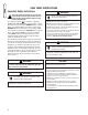
SAVE THESE INSTRUCTIONS Important Safety Instructions This is the safety alert symbol. It is used to alert you to potential personal injury hazards. Obey all safety messages that follow this symbol to avoid possible injury or death. The safety alert symbol ( ) is used with a signal word (DANGER, CAUTION, WARNING), a pictorial and/or a safety message to alert you to hazards. DANGER indicates a hazard which, if not avoided, will result in death or serious injury.
INTRODUCTION NOTICE These devices comply with Part 15 of the FCC Rules. Operation of the devices is subject to the following: (A) The devices may not cause harmful interference, and (B) The devices must accept any interference that may cause undesired operation. This equipment has been tested and found to comply with the limits for a Class B digital device, pursuant to Part 15 of the FCC Rules.
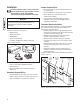
Installation Installer Responsibilities Read this Installation section carefully and become familiar with Homeowner Responsibilities, Installer Responsibilities, and the figures BEFORE contracting or starting your StatStation installation. NOTICE Power must be disconnected from display console and transmitter during the entire installation process or component failure will occur.
Sensing Wire Interconnections WARNING CAUTION Improper installation can cause damage to the circuit boards and shorten their life. Installing circuit boards in live circuits will damage the board is not a warranty condition. ALWAYS disconnect ALL sources of power prior to installation. • Remove all power prior to installing this wireless StatStation equipment. Failure to do so could cause internal damage to the components when making electrical connections. • Turn generator to OFF position.
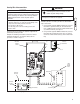
3. Using installer supplied 18AWG stranded wire, connect transmitter’s 9th terminal from left on J4 to ‘R’ terminal on transfer switch control board (J7, 3rd terminal from left). 4. Using installer supplied 18AWG stranded wire, connect transmitter’s rightmost J4 terminal to ‘+V’ terminal on transfer switch control board (J7, rightmost terminal). 5. Using installer supplied 18AWG stranded wire, run sufficient length of a pair of wires through conduit from transfer switch to generator.
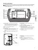
Controls and Features Read this operator’s manual and safety rules before operating your wireless StatStation. Compare the illustrations with your display console to familiarize yourself with the locations of various controls and features. Save this manual for future reference. A B G C H D I E H F A - Signal Strength — The number of bars to the right of the signal strength symbol indicate how strong the signal is between display console and transmitter.
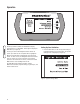
Operation Figure 4: Main Menu Touch any button to activate the StatStation’s display console when it is in Idle Mode Touch again to display the Main Menu (see Figure 4). Pressing one of the two Navigation buttons directs the cursor up or down so the next option will be highlighted. When the desired option is highlighted, touch the Select button. In some screens, the Navigation and Select buttons help you execute on-screen instructions.
2. Select Date & Time. Follow on-screen commands within Date Adjust to set the date and do the same in Time Adjust to set the time. Note that Navigation buttons are used to set correct numbers and the Select button will move cursor from one position to the next. When all positions on the screen are set, select Finish. The correct time and date will now be displayed on the left side of the display (see Figure 4). Selecting Return to Previous Menu will again display the System Settings menu. 3.
8. Enter the 9-digit Serial Number from the label on the transmitter (see Controls and Features for location), following the instructions on the screen. When the last digit is selected, choose to Synchronize. 9. Select Confirm. After approximately 20 seconds, the display console will report that the system is “Synchronized” and return to Idle Mode. Or it may display a “System Sync Unsuccessful” message and return to the System Sync Mode. Refer to Troubleshooting if this message appears. 2.
Maintenance Generator Maintenance StatStation Maintenance If alkaline (2200mAH) batteries are used, display console will operate for up to 40 hours, if the AC/DC Converter is not used. The transmitter will operate for up to 60 hours after utility and generator power is lost. A System Alert will be reported if the transmitter’s batteries are low. The left side of the display will indicate if the display console’s batteries are low.
Troubleshooting The StatStation will report System Alerts for problems with your generator and standby system and the LED will flash red. An audible alarm will accompany Generator and Standby System Alerts. System Alert Mode – Generator Faults System Alert Display Low Battery Voltage Fault Cause 1. Generator battery is low. Fault Remedy 1. Recharge or replace generator battery. Low Oil Pressure 1. Engine oil level is low. 2. Engine oil leaks. 1. Generator circuit breaker open. 2. Fault in generator. 3.
System Alert Mode – Standby System Faults System Alert Display Switch G Coil Fail Switch U Coil Fail Generator Start Switch in OFF Position Fuse Fail One Wire Communication Fail Transmitter Battery Low Fault Cause 1. Transfer switch generator coil failure. 1. Transfer switch utility coil failure. 1. Generator start switch in OFF position. Fault Remedy 1. Contact authorized service center. 1. Contact authorized service center. 1. Set generator switch to AUTO position. 2.
Illustrated Parts List 1 2 3 4 Item 1 2 3 4 Part # 197138GS 202756GS 195728GS 201092GS Items Not Illustrated 202766GS 14 Description ASSY, Transmitter ASSY, Display Console TRANSFORMER, Current ADAPTER, AC/DC MANUAL, Installation & Operator’s
Warranty BRIGGS & STRATTON POWER PRODUCTS GROUP, LLC ACCESSORY WARRANTY POLICY Effective July 1, 2006 replaces all undated Warranties and all Warranties dated before July 1, 2006 LIMITED WARRANTY Briggs & Stratton Power Products Group, LLC will repair or replace, free of charge, any part(s) of the accessory that is defective in material or workmanship or both. Transportation charges on product submitted for repair or replacement under this warranty must be borne by purchaser.
Reserved