Commercial High Efficiency Water Heater USE & CARE MANUAL WITH INSTALLATION INSTRUCTIONS FOR THE CONTRACTOR For use with the following models: GHE80SS, GHE80SU GHE100SS, GHE100SU CATEGORY IV Models Fan Assisted Combustion ! ! Recognize this symbol as an indication of important safety information! ! NOTICE: This water heater is designed for use in a commercial application and the installation and maintenance of it should be performed by a qualified, licensed service professional.
READ ALL SAFETY INFORMATION TABLE OF CONTENTS Safety Information Your safety and the safety of others are very important. There are many important safety messages in this manual and on your appliance. Always read and follow all safety messages. Safety Precautions. . . . . . . . . . . . . . . . . . . 3-4 Introduction Local Installation Regulations. . . . . . . . . . . . 5 Water Heater Location. . . . . . . . . . . . . . . . . . 5 ! Installation Instructions Inspect Shipment . . . . . . . . . . . . . .
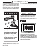
! General Safety Precautions To meet commercial water use needs, the temperature on this water heater is adjustable up to 185°F (85° C). However, water temperatures over 125°F (52° C) can cause severe burns instantly or death from scalds. This is the preferred starting point for setting the control for supplying general purpose hot water.
! General Safety Precautions Be sure to read and understand the entire Use & Care Manual before attempting to install or operate this water heater. Especially the following General Safety Precautions. Failure to follow these warnings could result in a fire or explosion, causing property damage, bodily injury, or death. Should you have any problems understanding the instructions in this manual, STOP, and get help from a qualified installer, service technician, or gas supplier.
Introduction LOCAL INSTALLATION REGULATIONS This water heater must be installed in accordance with these instructions, local codes, and utility company requirements. In the absence of local codes, the latest edition of the National Fuel Gas Code, ANSI Z223.1 in the United States, or CAN/CSA B149.1 Installation Codes in Canada should be consulted. sealing kit is available from the distributor or store where the water heater was purchased.
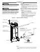
Installation setting of the relief valve, causing it to operate during each heating cycle. Thermal expansion, and the resulting rapid, repeated expansion and contraction of components in the water heater and piping system can cause premature failure of the relief valve and possibly the heater itself. Replacing the relief valve will not correct the problem! 3.
Installation the manual gas shut-off valve near the water heater. Use a soapy water solution to test for gas leaks at all connections and fittings. Bubbles indicate a gas leak that must be corrected. The water heater factory connections to the gas valve should also be leak tested after placing the water heater in operation. NEVER use open flame to test for gas leaks, as bodily injury or property damage could result.
Installation 7. VENTING — ! WARNING Failure to properly vent the water heater to the outdoors as outlined above and in the following section can result in unsafe operation of the water heater causing bodily injury, explosion, fire or death. ! WARNING NOTICE: DO NOT use in conjunction with a GFCI. To avoid the risk of fire, explosion or asphyxiation from carbon monoxide, NEVER operate this water heater unless it is properly vented and has an adequate air supply for proper operation.
Installation alent length of pipe that can be used. DO NOT exceed the equivalent length of pipe in the charts. CPVC (Schedule 40 DWV, ASTM F-438) ABS (Schedule 40 DWV, ASTM D-2661)(Not permitted in Canada) NOTICE: Use of PVC cellular core (ASTM-F891), ABS Schedule 40, DWV cellular core (ASTM –F628), or Radel® (polyphenylsulfone) in non-metallic venting systems is prohibited. The unit may be vented horizontally through a wall or vertically through the roof.
Installation • • Be sure the condensate runs freely to a drain and does not accumulate inside the water heater. In cold climates, precautions may need to be taken to insure that the condensate drain does not freeze. Make sure the condensate trap or drain loop is installed to prevent flue gases from being discharged into the room. Refer to the "Venting" section (page 8) of this manual for complete instructions on venting and condensate drainage.
Installation MINIMUM AND MAXIMUM VENT LENGTHS Feet Important information for all installations: to Meters 1) The minimum required venting is what is required to safely extend the inlet and outlet vent pipes outside of the building. 20 6.1 50 15.2 2) Each 90° elbow (standard or long sweep elbow) reduces the equivalent vent length by 5 feet (1.5m). 60 18.3 3) E ach 45° elbow reduces the equivalent vent length by 2 1/2 feet (0.8m). 70 21.3 80 24.4 100 30.5 120 36.6 130 39.6 170 51.
Installation Power Direct Vent Inlet Models GHE80SU-130(A) or GHE80SU-160(A) GH80SU-200(A) or GHE80SU-300(A) GHE100SU-130(A) or GHE100SU-160(A) GH100SU-200(A) or GHE100SU-250(A) or GHE100SU-300(A) GHE100SU-350(A) or GHE100SU-400(A) Max Vent Length (Eq.Ft.) Rigid Pipe Diameter 3" (8 cm) 4" (10 cm) Inlet Outlet Inlet Outlet Altitude Range 2" (5 cm) Inlet Outlet 0-2000 (0 - 609 m) 20 (6.1 m) 35 60 75 120 135 (10.7 m) (18.3 m) (22.9 m) (36.6 m) (41.1 m) N/A N/A 2001-8999 (610 - 2743 m) 20 (6.
Installation vent terminal is at least 2 feet (0.61 m) away from anything that can be damaged by the condensate HORIZONTAL VENT INSTALLATION – Once the vent terminal location has been determined, make a hole through the exterior wall to accommodate the vent pipe. The vent pipe must exit the exterior wall horizontally only (See Figure 6). Insert a small length of vent pipe through the wall, and connect the coupling as shown in Figure 6.
Installation Figure 8 G v H A D E V C B B C V L F I v X X v B LE RAB OPE M v ED FIX ED S CLO v ED FIX ED S CLO v E RABL OPE B v A K J B V VENT TERMINAL AREA WHERE TERMINAL IS NOT PERMITTED X AIR SUPPLY INLET Horizontal Vent Terminal Location for Power Direct Vent The following information should be used for determining the proper location of the vent terminal for direct vent water heaters.
Installation •D O NOT terminate near soffit vents or crawl space or other area where condensate or vapor could create a nuisance hazard or cause property damage. •D O NOT locate the exhaust vent terminal where condensate or vapor could cause damage or could be detrimental to the operation of regulators, relief valves, or other equipment. •D O NOT locate the exhaust vent terminal over public area or walkways where condensate or vapor can cause nui sance or hazard.
Installation Figure 9 G v H A D E V C B B C V L I v X B v A K X v B LE RAB OPE F M v ED FIX ED S CLO v ED FIX ED S CLO v E RABL OPE J B V VENT TERMINAL AREA WHERE TERMINAL IS NOT PERMITTED X AIR SUPPLY INLET Horizontal Vent Terminal Location for Power Vent The following information should be used for determining the proper location of the vent terminal for direct vent water heaters.
Installation Figure - 10- Typical Horizontal Power Vent System EVERY 3' MAX. When 6 inch pipe is used, start pipe supports as close as possible to unit. SUPPORT BRACKET 2, 3, 4, OR 6* INCH PIPE AND FITTINGS 45° TERMINAL 1 IN. MAX. WATER HEATER WALL DRAIN PAN FLOOR * A 6 inch pipe can be used on 300,000 Btu/h models and above.
Installation Figure - 11- Typical Horizontal Direct Vent System EVERY 3' MAX. SUPPORT BRACKET When 6 inch pipe is used, start pipe supports as close as possible to unit. 2, 3, 4, OR 6* INCH PIPE AND FITTINGS 45° TERMINAL 1 IN. MAX. WATER HEATER WALL DRAIN PAN FLOOR * A 6 inch pipe can be used on 300,000 Btu/h models and above. Through The Wall Venting With Low Ground Clearance: When venting cannot exit through the wall at a height greater than or equal to 12” (30.
Installation Horizontal Venting Figure 12a: Multiple Unit Venting Figure 12c: Optional Configuration Example of 2 Units' Vents. 24" to 36" Heater #1 Intake 24" to 36" Heater #2 24" Min. Intake Exhaust 24" to 36" Heater #1 Exhaust Intake Figure 12b: Multiple Unit Venting 10" Min. 24" to 36" Heater #2 Exhaust Exhaust Intake Figure 11d: Optional Configuration NOTICE: 11c can also be configured for 4 units. 24" to 36" Heater #1 Example of 4 Units' Vent. 24" Min.
Installation Figure 13. Typical Vertical Direct Vent System Installation Straight Exhaust Terminal 24" (61 CM) Min (Support required). 90° Intake Terminal "D" Support Bracket Water Heater "D" Min. 18 in. (46 cm) above Roof Min. 12 in. (30.5 cm) above anticipated snow level ax. 24 in. (61 cm) above roof without M additional support) Floor Alternate vertical venting with exhaust vent turned down - preferred for cold climates. Terminals with 1/2 in. (1.
Installation Figure 14. Typical Vertical Power Vent System Installation Min. of 18" (46 cm) above roof. Straight Exhaust Terminal Min. of 12" (30.5 cm) above anticipated snow level. Max. 24" (61 cm) above roof without additional support. Support Bracket Recommended support bracket be placed on horizontal run 90° Combustion Air Inlet Terminal with screen Water Heater Floor Alternate vertical venting with exhaust vent turned down preferred for cold climates. Exhaust Terminal Min.
Installation Figure 15.
Installation CONCENTRIC VENT TERMINAL INSTALLATION: PROCEDURE Improper installation, adjustment, service, or maintenance can cause property damage, personal injury, or death. Consult a qualified installer, service agency, or gas supplier for information or assistance. ! CAUTION DO NOT operate this water heater with the rain cap removed or recirculation of combustion products may occur. Water may also collect inside larger combustion-air pipe and flow to the burner assembly.
Installation STEP 3: Secure the combustion air-inlet pipe using a field supplied perforated strap or a suitable type material (see Figure 16). ! WARNING These instructions are intended as an aid to qualified service personnel for proper installation, adjustment, and operation of this kit. Read these instructions thoroughly before attempting installation, adjustment, or operation.
Installation STEP 3: Secure the combustion air-inlet pipe using a field supplied perforated strap or a suitable type material. (see Figure 18). Figure 19 Multiple Sidewall or Vertical Concentric Vents 36" (91 cm) Min. 36" (91 cm) Min. STEP 4: Assemble the vent pipe assembly by cleaning and cementing the rain cap to the smaller diameter exhaust pipe. Assemble the 90° elbow by cleaning and cementing it to the rain cap.
Installation The GHE80SS/SU and GHE100SS/SU models have been certified to use polypropylene pipe for both the intake and exhaust vent systems, but must use the current PVC vent terminations (including concentric vents). All polypropylene pipe and fittings listed in the tables below are ULC-S636 listed.
Installation PVC pipe shipped with the unit PVC to PP PP pipe adapter Straight piece of PP pipe connected to a PP to PVC adapter vent terminal installed onto a PP to PVC adapter. Note: The hole through the wall should be sized for the PP pipe, which has a smaller OD than PVC pipe. The first step to install the PP pipe is to find a PVC to PP adapter and lubricate the gasket that will slide into the PVC fitting. The lubricant for the Centrotherm parts is called Centrocerin.
Installation The PVC to PP adapter should then be installed into the PVC couplings on the inlet air and exhaust vent installed on the unit. The sealing gasket will require some type of lubricant to make it easier to install the adapter. Both Centrotherm and M&G Duravent recommend a connector ring to be installed between the PVC part and the PP part. The connector ring for the Centrotherm pipe (either IAFC02, IAFC03, or IAFC04) is shown below.
Installation To be able to use a PVC termination, a short piece of PP pipe will need to be cut, as shown below, to transition from the bell end of the pipe to the PP to PVC adapter. Cut a piece of PP pipe that is long enough to go through the wall and have about 2" protruding on each side of the wall. The PP to PVC adapter can either be installed on the pipe or into the vent terminal for the next step. The final step is to make sure the vent terminal is attached and secured to the adapter.
Installation Check List A. Water Heater Location D. Relief Valve ❑ Close to area of vent. ❑ Indoors and protected from freezing temperatures. ❑ Discharge line run to open drain. ❑ Discharge line protected from freezing. ❑P roper clearance from combustible surfaces observed and water heater is not installed on a carpeted floor. E.
Operation Before operating this water heater, be sure to read and follow the instructions on the label pictured below and all other labels and warnings on the water heater and printed in this manual. Failure to do so can result in unsafe operation of the water heater resulting in property damage, bodily injury, or death. Should you have any problems reading or understanding the instructions in this manual, STOP, and get help from a qualified person. . Call any phone in your building. instructions.
Operation SAFETY PRECAUTIONS F. I f there is any difficulty in understanding or following the OPERATION or MAINTENANCE instructions, it is recommended that a qualified person or serviceman perform the work. A. D O turn off manual gas shut-off valve if water heater has been subjected to over heating, fire, flood, physical damage or if gas supply fails to shut off. B. DO NOT turn on water heater unless it is filled with water. C.
User Interface NAVIGATING THE HOME SCREEN: Health Indicator Icons Operating Status Status: Standby Wifi Indicator and Settings 120° Temperature Setting warm hot Rapid Temperature Adjustment very hot Temperature Adjustment Settings Setting Menu Button Status Button Status Service Menu Button Startup Disable Service Enable/Disable Button Setting Menu Once power is applied to the water heater and the On button is pressed, the Startup Wizard on the LCD will go over the below features: 1.
User Interface BASIC SETTINGS: The basic settings in you water heater can allow you to change the temperature unit, screen adjustment lock/unlock, enabling/disabling the alarm beep, and your EcoNet network instance. Simply select the setting by tapping it, and press the Up/Down arrows to make adjustments. WiFi setup can be accessed from this screen as well. sponse can be selected to the following: • Open • Closed • Close if Leak Detected: Always close the valve when leak is detected. • Close if Unocc.
User Interface Status Menu MORE FUNCTION: Selecting the more function your heater will bring you to a prompt showing you the current temperatures of the lower/upper tank, Flue temperature, ECO switch state, and Auxiliary relay state. The Status screen provides information on the current operating status, diagnostics and sensors. This screen also provides information on the WiFi status.
User Interface ALARMS: The current alarms function allows you to see any problems that have been detected by your water heater. Also, by selecting on the current alarm you can press “more info” to read more on the current problem of your water heater. Alarm history allows you to see any of the previous alarms that have gone off in the past and give you the ability to clear those previous alarms.
Maintenance Properly maintained, this water heater will provide years of dependable, trouble free service. It is strongly suggested that a regular routine maintenance program be established and followed by the owner. It is further recommended that a periodic inspection of the relief valve and venting system should be made by service technicians qualified in gas appliance repair. Any new installation should have a tank inspection program set up initially for frequent inspection.
Before You Call For Service… Troubleshooting Tips Status: Standby Save time and money! Review the charts on the following pages first and you may not need to call for service. 120° If one of the health indicators is blinking on the home screen or the service icon is blinking there is an issue with the operation of your water heater. Pressing the service icon will allow you to look at Current Alarms (and Alerts), Alarm History, and Unit Health screenswarm for issues that need attention.
Before You Call For Service… Troubleshooting Tips Save time and money! Review the charts on the following pages first and you may not need to call for service. Problem Unable to light the main burner Main burner does not stay lit Not enough or no hot water Water is to hot Possible Cause What To Do Gas control ploblem Contact a qualified service technician. Unit or electrical supply line not properly grounded Verify that the electrical supply line and unit have proper ground connection.
Before You Call For Service… Alarm (‘A’) and Alert (‘T’) Codes Description Current Alarm Screen Display A001 Ignition lockout due to a total of 9 consecutive failed ignitions. This will disable the heater. A001 Ignition lockout. ->Clear error code by turning the unit off/on. If problem persists, please contact technical support or service provider. A002 Flame not stable lockout. Lost flame three times during one heat cycle. This will disable the heater. A002 Flame is not stable.
Before You Call For Service… Alarm (‘A’) and Alert (‘T’) Codes Description Current Alarm Screen Display A016 Energy Cutout (ECO) switch is open. This will disable the heater. A016 High Tank Temperature. Call Tech Service. ->Clear error code by pressing clear button. Refer to use and care manual for troubleshooting, or contact technical support. A017 Flue (exhaust) gas temperature has exceeded 155°F. This will disable the heater. A017 High Flue Temp. Recycle unit ON/OFF.
Before You Call For Service… Alarm (‘A’) and Alert (‘T’) Codes Description Current Alarm Screen Display A025 Control does not detect blower RPM. This will disable the heater. A025 No Blower RPM feedback. Call Tech Service ->Please contact technical support or service provider. A026 Blower RPM feedback (actual RPM) is ≥300 RPM from desired RPM for > 1 minute. A026 Blower expected RPM vs actual RPM mismatch ->Please contact technical support or service provider.
Before You Call For Service… Alarm (‘A’) and Alert (‘T’) Codes Description Current Alarm Screen Display A037 Gas relay #2 contacts failed to properly close. This can cause gas valve cycling and gas buildup in the burn chamber. This will disable the heater. A037 Gas Relay 2 stuck open. Call Tech Service ->If problem persists, please contact technical support or service provider. A038 Gas relay #2 stuck closed. This could inadvertently allow the gas valve to open. This will disable the heater.
Before You Call For Service… Alarm (‘A’) and Alert (‘T’) Codes Description Current Alarm Screen Display T105 T105 Water Leak Sensor Not Installed Check to see if leak sensor is installed in the bot->Check water leak sensor connection. Refer tom pan. Check wiring on connector P11 of the to use and care manual for troubleshooting, or ignition control board. contact technical support. A108 Communication lost between the display board and the ignition control board.
Before You Call For Service… Alarm (‘A’) and Alert (‘T’) Codes Description Current Alarm Screen Display T117 Periodic maintenance, inspection, and upkeep on the unit. T117 Time to Drain and Inspect Tank ->Refer to the use and care manual for instructions, or contact technical support or service provider. T118 Periodic maintenance, inspection, and upkeep on the unit.
Before You Call For Service… Alarm (‘A’) and Alert (‘T’) Codes Description Current Alarm Screen Display T128 Anode “open” circuit. This can be caused by wiring damage, wiring disconnected, or anode damage. T128 Middle Anode Open ->Check wiring connections for the middle anode. If error persists, please contact technical support or service provider. T129 Anode control common and the power connection for this anode cross connected.
Replacement Parts Instructions For Placing a Parts Order All parts orders should include: Part description (as noted below) and number of parts desired. The model and serial number of the water heater from the rating plate. ! Specify type of gas (natural or LP) as marked on the rating plate. AUTION: For your safety DO NOT attempt repair of gas piping, C gas control burner, vent connectors or other safety devices. Refer repairs to qualified service personnel.
Wiring and Schematic Diagrams AX5631 ! CAUTION Label all wires prior to disconnection when servicing controls.
NOTES: 49
NOTES: 50
NOTES: 51
How to Obtain Service Assistance 1. Should you have any questions about your new water heater, or if it requires adjustment, repair, or routine maintenance, it is suggested that you first contact your installer, plumbing contractor or previously agreed upon service agency. In the event that the firm has moved, or is unavailable, refer to the telephone directory commercial listings or local utility for qualified service assistance.