
Instructions / Assembly


10
• For applications below 32°F (0°C), use only low
temperature type solvent cement.
• Appropriate solvent and cleaner must be used
for the type of vent pipe used (PVC, CPVC, PP,
or ABS).
DANGER OF FIRE OR BODILY INJURY – Solvent
cements and primers are highly flammable. Provide
adequate ventilation and do not assemble near a
heat source or open flame. DO NOT smoke. Avoid
skin or eye contact. Observe all cautions and warn-
ings on material containers.
DIRECT VENT INSTALLATION - Check to make sure
flue gases DO NOT recirculate into the air intake
terminal when using direct venting. If the water heat-
er is having service issues, flue recirculation may be
a contributing factor. Even when the minimum vent
terminal separation distances are followed,
recirculation may still occur, depending upon the
location outside the building, the distance from other
buildings, proximity to corners, weather conditions,
wind patterns, and snow depth. Periodically check
to make sure that flue recirculation is not occurring.
Signs of flue gas recirculation include frosted or fro-
zen
intake terminals, condensate in the intake terminal
and venting system, oxidation, or white chalk mate-
rial on the flame sensor or igniter shield. Correction
to flue recirculation may involve angling the intake
away from the exhaust terminal, increasing the dis-
tance
between them, or using inside air for combustion.
Check to be sure the intake and exhaust terminals
are not obstructed, especially during periods of
below freezing weather.
All intake and exhaust venting components must
have the same diameter size. DO NOT use a different
size on the intake and exhaust venting.
Be sure the condensate runs freely to a drain and
does not accumulate inside the water heater. In cold
climates, precautions may need to be taken to insure
that the condensate drain does not freeze. Make
sure the condensate trap or drain loop is installed to
prevent flue gases from being discharged into the
room. Refer to the "Venting" section (page 8) of this
manual for complete instructions on venting and
condensate drainage.
Stress levels in the pipe and fittings can be
significantly increased by improper installation. If
rigid pipe clamps are used to hold the pipe in place,
or if the pipe cannot move freely through a wall
penetration, the pipe may be directly stressed, or
high thermal stresses may be formed when the pipe
heats up and expands. Install accordingly to mini-
mize such stresses. Follow the below procedure to
vent through the wall.
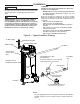
1. Cut two holes for the pipe to pass through. The hole
diameter should be 2.5" (6.4 cm) for 2" pipe, 3.5"
(8.9 cm) for 3" pipe, and 6.5" (16.5 cm) for 6" pipe.
Vent terminals must maintain a horizontal distance
apart in the range of 24" to 36" (61 cm to 91 cm).
Refer to Figure 5 for additional information.
2. Use the proper PVC cement (primer and adhesive)
to secure the exhaust vent and air intake terminals
provided with the water heater to the plastic pipes.
The distance between the back edge of the exhaust
vent terminal and the exterior wall (see Figure 10)
must be 6 inches (12.7 cm) more for the exhaust vent
terminal than the air intake terminal. Use the
proper cement or sealant and assembly procedures to
secure the vent connector joints between the
terminal and the blower outlet. Provide support
brackets for every 3 feet (.91 m) of horizontal vent
beyond the intake terminal as seen in Figure 10.
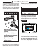
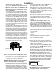
Additional Fitting Considerations
Long Sweep 90°
Elbow
Best
DO NOT use
Short Sweep 90°
Elbow
Good
Standard 90°
Elbow
Figure - 5. Examples of Elbows:
DO NOT use short sweep elbows.
It is recommended to use only
standard and/or long sweep
elbows. See examples as shown.
Installation