
Instructions / Assembly


7
the manual gas shut-off valve near the water heater.
Use a soapy water solution to test for gas leaks at all
connections and fittings. Bubbles indicate a gas leak
that must be corrected. The water heater factory
connections to the gas valve should also be leak
tested after placing the water heater in operation.
NEVER use open flame to test for gas leaks, as
bodily injury or property damage could result.
PRESSURE TESTING THE GAS SUPPLY SYSTEM —
The water heater and its manual gas shut-off valve
MUST be disconnected from the gas supply piping
system during any high pressure testing of that
system at pressures in excess of 1/2 psi (14” WC.
3.5 kPa).
The water heater MUST be isolated from the gas
piping system by closing the manual gas shut-off
valve during any pressure testing of the gas supply
piping at pressures equal to or less than 1/2 psi (14”
WC / 3.5 kPa).
5.
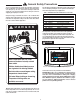
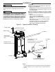
CONDENSATE
EXHAUST TEE & NEUTRALIZER -
The exhaust
elbow/condensate trap is located in the instal-
lation kit along with the bag of neutralizer. Pour
the neutralizer into the exhaust tee so that it is in
the bottom. Then insert the exhaust tee onto the
heater as shown in Figure 1. Using a 5/16" nut
driver or ratchet, tighten the exhaust tee onto the
heater.
CONDENSATE -
This is a condensing high effi-
ciency appliance and has a condensate removal
system. The exhaust tee incorporates a conden-
sate trap and must be filled with water before
operating the water heater. Pour about 1 cup of
water into the exhaust tee.
SERVICING -
Remove the exhaust elbow from the
heater using a 5/16" nut driver or ratchet. Empty
the condensate and neutralizer from the ex-
haust elbow, and refill it with the new neutralizer
(Rheem part number AP16770). Re-attach the
exhaust tee to the heater. Pour approximately 1
cup of water into the exhaust tee. Re-attached
the venting
. It is very important that the condensate
line is sloped away from the heater and down to a
suitable inside drain. If the condensate outlet on
this unit is lower than the drain, you must use a con-
densate removal pump. It is also important that the
condensate line is not exposed to freezing tempera-
tures, or any other type of blockage. Plastic tubing
should be the only material used for the condensate
line. Steel, brass, copper, or other metals will be
subject to corrosion and deterioration, so they are
not recommended to be used for the condensate
drain line. A second vent may be necessary to pre-
vent condensate line vacuum lock if a long horizon-
tal run is used. Also an increase to 1" tubing may be
necessary.
6. WIRING — A correct polarity 120V 50/60 Hz power
supply with suitable disconnect means, must be
connected to the black and white leads provided.
The maximum current draw by these models is 7
Amps. The water heater, when installed, must be
electrically grounded in accordance with local codes
or, in the absence of local codes, with the National
Electrical Code, ANSI/NFPA 70 in the
United States, or CSA C22.1 Electrical Code, in Can-
ada. Improper grounding or polarity may result in ab-
normal operation of the unit. Refer on page 48 of this
manual for the wiring diagram for this water heater.
The water heater must be vented to the outdoors
as described in these instructions.
DO NOT connect this water heater to an existing vent or
chimney; it must be vented separately from all other ap-
pliances, using only approved venting materials.
Installation
Figure 1
Figure 2 - Condensate Trap
WA RNING
!
WA RNING
!
Complete installation of wiring harnesses per in-
stallation instructions in kit.