Power Vent / Intellivent with FVIR Classroom Contents: ● ● ● GTC 070 r3 Intellivent Service Handbook Technical Bulletin Intellivent with FVIR Technical Bulletin Pressure Switches
INTELLI-VENT™ CONTROL INFORMATION When Used On Gas, Residential, Power Vented Water Heaters Printed in the USA – 0605 Part No. GTC-070 R3 Revision 2 includes updated troubleshooting information for error codes 3, 4, and 6.
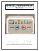
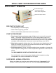
INTELLI-VENT TROUBLESHOOTING GUIDE INTELLI-VENT™ FEATURES The Intelli-Vent™ is a combination control incorporating all temperature control, ignition control, blower and ignitor control, flame sensing, and gas regulation into a single device. Advanced Diagnostics - Error Codes The Intelli-Vent™ features advanced diagnostics with 15 specific error codes including reversed polarity and inadequate grounding notification. Diagnostic information is conveyed via 6 LED lights on the control.
INTELLI-VENT TROUBLESHOOTING GUIDE INTELLI-VENT™ CONSTRUCTION 6 LED indicator lights Temperature Probe/ECO • Temperature Settings • Error Codes / Diagnostics Supply Gas Connection Temperature adjust buttons Future side connect model is shown here. Top connect models are in use currently. Temperature adjust buttons must be pressed together for one second to “wake up” the control in order to view or change temperature settings.
INTELLI-VENT TROUBLESHOOTING GUIDE INTELLI-VENT™ OPERATION 6 LED indicator lights • Temperature Settings • Error Codes / Diagnostics Temperature adjust buttons PRE START UP CHECK LIST • Correct polarity on electrical supply • Water heater is properly grounded • Owner’s manual safety statements have been reviewed START UP PROCEDURE 1 Plug in water heater and turn on power. All lights on the control will come on for about 1 - 5 seconds. All lights will then turn off.
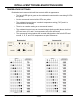
INTELLI-VENT TROUBLESHOOTING GUIDE TEMPERATURE SETTINGS Residential and commercial Intelli-Vent controls differ in appearance: • The far left LED light is green on the residential control and the remaining 5 LEDs are yellow. • On the commercial control all six LEDs are yellow. • The residential control has a “vacation’ temperature setting (70°F) and it is referenced on the display. • There is no vacation setting on a commercial control.
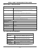
INTELLI-VENT TROUBLESHOOTING GUIDE INTELLI-VENT™ SPECIFICATIONS INTELLI-VENT™ CONTROL SPECIFICATIONS Body ½ inch NPT inlet. ½ inch inverted flare outlet. (RH thread natural, LH thread propane) Electrical Ratings 120 VAC, 60 Hz, 1Ø, 5-7 FLA. Ignitor load: 2 amps maximum. Blower/inducer motors: 3 amps full load - 4 amps locked rotor. Max Inlet Gas Pressure ½ PSI maximum (14.0" W.C.) Temperature Range 70 - 160°F Residential. 120 - 180°F Commercial.
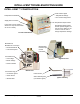
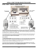
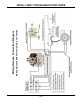
INTELLI-VENT TROUBLESHOOTING GUIDE INTELLI-VENT™ WIRING CONNECTIONS FEMALE MOLEX RECEPTACLES BOTTOM OF CONTROL Ignitor Assembly Connections Wiring Harness Connections Female Receptacle Female Receptacle Male Plug Male Plug 1. = Air Pressure Switch Circuit 2. = 120 VAC Neutral Wire to Blower 3. = 120 VAC Hot Wire to Control 4. = Air Pressure Switch Circuit 5. = 120 VAC Hot Wire to Blower 6. = 120 VAC Neutral Wire to Control 1. = Ignitor hot wire 2. = Ignitor neutral wire 3. = Resistor wire 4.
Models Equipped With Vent Temperature Limit Switch Wiring Harness Connection Diagram INTELLI-VENT TROUBLESHOOTING GUIDE Technical Training Department Ashland City, Tennessee © 2005 7 of 24
INTELLI-VENT TROUBLESHOOTING GUIDE INTELLI-VENT™ SEQUENCE OF OPERATION Technical Training Department Ashland City, Tennessee © 2005 8 of 24
INTELLI-VENT TROUBLESHOOTING GUIDE INTELLI-VENT™ TROUBLESHOOTING GUIDE Error Codes & Diagnostics The Intelli-Vent™ control will not have any LED lights illuminated during normal operation (sleep mode) for the life of the water heater. When an LED is illuminated, it draws attention to the water heater and the need to have it serviced. There are 15 different diagnostic error codes the Intelli-Vent™ control is capable of displaying by illuminating various combinations of LED lights.
INTELLI-VENT TROUBLESHOOTING GUIDE ERROR CODE 2 - REVERSED POLARITY 2 Power supply to Intelli-Vent™ control has reversed polarity. Check / Repair: • Insure the wall outlet is properly wired. • Insure all internal 120 VAC wiring connections on the water heater are not reversed. 120 VAC “hot” wire should connect to the on/off switch. • Insure the wiring harness between the Intelli-Vent control and the wiring box has no crossed wires with an ohm meter.
INTELLI-VENT TROUBLESHOOTING GUIDE ERROR CODE 4 - PRESSURE SWITCH CIRCUIT REMAINS OPEN 4 Pressure switch circuit (see 7) remains open longer than 5 seconds after the combustion blower/inducer fan was energized by the Intelli-Vent™ control. Blower may run continuously in this condition.
INTELLI-VENT TROUBLESHOOTING GUIDE ERROR CODE 5 - IGNITOR FAILURE 5 The Intelli-Vent™ control has detected an open ignitor circuit. Check / Repair: • Check all wiring to the hot surface ignitor. • Check 5 pin Molex ignitor assembly plug and receptacle on the Intelli-Vent™ body for a good connection. Repair or replace parts if necessary. • Check resistance of ignitor with an ohm meter between pin 1 and 2 on the ignitor assembly plug. Replace ignitor if resistance is not within 11.5 and 18.8 ohms.
INTELLI-VENT TROUBLESHOOTING GUIDE ERROR CODES - 7, 8, 9 - INTERNAL CONTROL FAILURES 7 8 9 Self diagnostic tests have found a problem with the gas valve driver circuit, internal microprocessor, or the internal circuits. Check / Repair: • Turn the power off for 10-20 seconds then on again to clear these error codes. • If any of these error codes persist or cannot be cleared - replace the Intelli-Vent™ control.
INTELLI-VENT TROUBLESHOOTING GUIDE ERROR CODE 11 - HIGH TEMPERATURE CUTOFF (ECO) ACTIVATED 11 Water temperature in the tank exceeded 195°F and activated the ECO. Check / Repair: • Turn the power off for 10-20 seconds and then on again to clear this error code. • Residential control - replace the control if the error code cannot be cleared. • Commercial control - cool water temperature below 120°F, cycle power off and on to reset control. Replace the control if the error code persists.
INTELLI-VENT TROUBLESHOOTING GUIDE ERROR CODE 14 - RESISTOR WIRE OPEN OR SHORTED 14 The self-diagnostic test found a problem with the black resistor wire on the ignitor assembly plug; the resistor wire is open or shorted. (see 6) Check / Repair: • Insure the black resistor wire is not cut, missing, and is installed between pins 3 & 4 of the ignitor assembly plug. Replace ignitor assembly if damaged or defective. • Unplug the ignitor assembly plug from the control.
INTELLI-VENT TROUBLESHOOTING GUIDE TECHNICAL BULLETIN - IGNITION AND FLAME FAILURE A-022-04 & S-021-04 COMBINED This technical bulletin has been prepared to help diagnose and repair ignition and flame failure problems with White Rodgers Intelli-Vent equipped water heaters. Procedures to verify correct flame sensor alignment, burner assembly condition, and flue restrictor/baffle position are outlined in this bulletin.
INTELLI-VENT TROUBLESHOOTING GUIDE FLAME SENSOR ALIGNMENT (CONT) Technical Training Department Ashland City, Tennessee © 2005 17 of 24
INTELLI-VENT TROUBLESHOOTING GUIDE BURNER CHECK LIST REMOVE BURNER TO PERFORM THE FOLLOWING TESTS 1 Burner mounting screws. Check the two mounting screws that hold the burner head to the main burner tube. These screws being loose can cause poor burner grounding and diminished or lost flame sensing current which leads to burner short cycling and lockout.? 2 Ignitor assembly plug connection.
INTELLI-VENT TROUBLESHOOTING GUIDE FLUE BAFFLE & FLUE RESTRICTOR CHECK Flue baffle assembly shown to the left. Insure this is assembled and installed properly. This can become dislodged during transport. Always check the flue baffle assembly if the water heater has been laid on its side during transport. Some power vent residential models are equipped with flue restrictors in addition to the flue baffles installed on all models.
INTELLI-VENT TROUBLESHOOTING GUIDE TECHNICAL BULLETIN - AIR PRESSURE SWITCHES A-023-04 & S-024-04 COMBINED Air pressure switches are used on all fan assisted gas fired water heaters, residential and commercial. If the water heater was factory equipped with a combustion blower or inducer fan, by design the blower must running during the heating cycle.
INTELLI-VENT TROUBLESHOOTING GUIDE AIR PRESSURE SWITCH CONSTRUCTION The switch below has normally open switch contacts that close on a fall in pressure. Normal State Sensing port Activated State Wiring terminals Switch contacts Diaphragm Vent port AIR PRESSURE SWITCH OPERATION Air pressure switches activate in response to changes in air pressure sensed through a plastic tube attached to a sensing port on the water vent system and/or blower housing.
INTELLI-VENT TROUBLESHOOTING GUIDE AIR PRESSURE SWITCHES - DIFFERENT TYPES SWITCH CONTACTS SWITCH ACTION Normally Open = NO Close on a rise in pressure Close on a fall in pressure Open on a rise in pressure Open on a fall in pressure Normally Closed = NC The switches shown here are all SPST switches. SPST = single pole, single throw. Power Vent and Power Direct Vent residential products use the first type shown below. Normal State Activated State Normally open contacts, close on a fall in pressure.
INTELLI-VENT TROUBLESHOOTING GUIDE AIR PRESSURE SWITCH TESTING Continuity test with ohm meter Taking an air pressure reading To test the performance of an air pressure switch you must know the design activation point. This will be a given pressure value, either negative (in a vacuum) or a positive pressure. Contact the technical information center for this information or to locate a service handbook for the product you are working on. A. O. Smith Water Heaters; 800 527-1953.
INTELLI-VENT TROUBLESHOOTING GUIDE AIR PRESSURE SWITCH CIRCUITS Air Pressure Switch Circuit - Residential Power Vent/Power Direct Vent Blocked Exhaust Switch Normally Open Contacts Close on a Fall in Pressure Vent Temperature Limit Switch Normally Closed Contacts Open on a Rise in Temperature 1 Molex Plug 6 Pin Plug 4 Technical Training Department Ashland City, Tennessee © 2005 24 of 24
No.: ARGPN0305N Date: March 18, 2005 Vent Termination Restrictor Usage for 40,000 Btu Power Vent Models This bulletin will simplify vent termination restrictor usage for the 40,000 Btu power vent models and allowable venting distances. Power vent models, 40,000 Btu, manufactured prior to November 2004 (serial number K04) are shipped with a vent kit that includes a 2" restrictor (1 ¾” inside opening) and 2” tee.
No.: S425 Date: 10/21/04 Vent Termination Restrictor Usage for 40,000 Btu Power Vent Models This bulletin will simplify vent termination restrictor usage for the 40,000 Btu power vent models and allowable venting distances. Power vent models, 40,000 Btu, manufactured prior to November 2004 (serial number K04) are shipped with a vent kit that includes a 2" restrictor (1 ¾” inside opening) and 2” tee.
Additional copies are available from the Ashland City Advertising Department Prepared by the A. O.
TB-A028-06 - A. O. SMITH - FVIR INTELLI-VENT TROUBLESHOOTING CHART # 1 2 3 LED STATUS PROBLEM Inadequate or no earth ground sensed by the Intelli-Vent™ control. 1 Ensure the wall outlet is properly grounded. Power supply to Intelli-Vent™ control has reversed polarity. 1 Ensure the wall outlet is properly wired. Pressure switch circuit remaining closed for more than 5 seconds after heating cycle begins. Blower does not start.
TB-A028-06 - A. O. SMITH - FVIR INTELLI-VENT TROUBLESHOOTING CHART # LED STATUS PROBLEM Ignition/flame failure. 6 The water heater has reached the maximum number of retries and is currently locked out for one hour. Cycle the power to the water heater off and on to reset. SOLUTION 1 Gas supply is turned off - pressure too low. Ensure supply and manifold gas pressures are within requirements in the installation manual. Manifold gas pressure is non-adjustable if pressure is off by more than 0.3” W.C.
TB-A028-06 - A. O. SMITH - FVIR INTELLI-VENT TROUBLESHOOTING CHART # 14 LED STATUS PROBLEM SOLUTION The self diagnostic test has detected the flammable vapor sensor is either open or shorted. 1 Turn off power to the water heater. Ensure all FV sensor wiring, the ignitor assembly plug, and the ignitor assembly socket on the bottom of the IntelliVent™ control are making good contact. Repair or replace any worn/damaged components that are not making a good connection.
TB-A028-06 - A. O. SMITH - FVIR INTELLI-VENT TROUBLESHOOTING CHART # 15 LED STATUS PROBLEM The self diagnostic test has detected the presence of flammable vapors. The Intelli-Vent control is programed to lock-out and display this error code if the resistance value it senses from the FV sensor is above 70,000 ohms but remains below 1,700,000 ohms. The Intelli-Vent control is in a hard lock-out condition that cannot be reset by cycling power to the water heater.
TB-A028-06 - A. O. SMITH - FVIR INTELLI-VENT TROUBLESHOOTING CHART # 16 LED STATUS PROBLEM LDO (Lint, Dust, and Oil) lockout condition. Air pressure switch circuit is opening repeatedly during one heating cycle. May be caused by the air pressure switch and/or the vent temperature limit switch (these two switches are wired together in a “series” circuit). SOLUTION 1 Check/clean intake air screen on the base ring of the water heater. 2 Check/clean the dilution air screen on the blower assembly.
Tuesday, January 16, 2007 Technical Bulletin TB-A023-06 Air Pressure Switches This bulletin has been prepared to explain and illustrate the construction, operation, and testing procedures for various types of air pressure switches used on residential and commercial tank type water heaters. Air pressure switches are used on all “fan assisted” gas fired water heaters in our product line.
Air Pressure Switch Construction Normal State (open switch contacts) Activated State (closed switch contacts) Wiring Terminals Sensing Port Switch Contacts Internal Linkage Flexible Diaphragm Vent Port Air Pressure Switch Operation Air pressure switches activate in response to pressure sensed through a tube. One end of this tube attaches to the pressure switch sensing port, the other end attaches to a pressure sensing port somewhere on the water heater, IE: the vent system, blower assembly.
Air Pressure Switch Operation (cont) Contact Actions: The “action” of the contacts refers to what causes the switch to activate, to change from it’s “normal state” to its “activated state” (see page 2). On an air pressure switch this can be either a rise or fall in pressure. As the illustrations below indicate, locating the sensing port above or below the flexible diaphragm facilitates these operational differences.
Air Pressure Switch Testing Continuity Test With Ohm Meter BTH 120 - 250 Blocked Exhaust Switch Continuity Test With Ohm Meter Power-Vent Residential Model Testing the performance of air pressure switches involves three procedures. First Procedure is a normal state test to determine if the switch contacts are open or closed in the normal state (see page 2) without pressure applied. Power is turned off for this test. The wires to the switch are disconnected.
Air Pressure Switch Testing (cont) The pressure activation point for the air pressure switch below is - 1.07" W. C. (inches water column) This is a negative pressure value – in a vacuum. Blocked Vent Air Pressure Switch Residential Power Vent Model Blocked Vent Switch - Pressure Test Vertex Residential Power Vent Model Third Procedure is a pressure test and requires a digital manometer capable of reading positive and negative pressures. A good range of operation would be +15.00 “W.C. to -15.00 “W.C.
Blocked Exhaust Switch Pressure Test Cyclone - BTH 300/400 Models Blocked Exhaust Switch Pressure Test Cyclone - BTH 120 - 250 Models Air Pressure Switch Testing Third Procedure - Normally Open Switches (cont): Pressure reading taken DOES NOT reach the activation pressure (cont): Ensure the sensing tube is connected securely and not blocked with any debris or condensate. Ensure the tube is not kinked or leaking.
Air Pressure Switch Types Contact States Contact Actions Normally Open = NO Normally Closed = NC Close on a rise in pressure Close on a fall in pressure Open on a rise in pressure Open on a fall in pressure Application Normal State Activated State Blocked Exhaust Air Pressure Switch Power-Vent & Power Direct Vent Residential Models Blower Prover Air Pressure Switch BTI/BTN 120 – 400 Models Normally open contacts, close on a fall in pressure.
Air Pressure Switch Circuit Residential Power-Vent & Power-Direct-Vent Water Heaters Blocked Exhaust Switch Normally Open Contacts Close on a Fall in Pressure Vent Temperature Limit Switch Normally Closed Contacts Open on a Rise in Temperature 1 Molex Plug 6 Pin Plug 4 Air Pressure Switch Circuit Cyclone Water Heater Blocked Inlet Switch Normally Closed Contacts Open on a Fall in Pressure Blocked Exhaust Switch Normally Closed Contacts Open on a Rise in Pressure 4 CN6 Plug Control Board Blower Prover
Intelli-Vent™ Sequence of Operation