
Troubleshooting guide
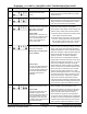
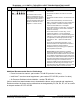

Testing the performance of air pressure switches involves three procedures.
First Procedure is a normal state test to determine if the switch contacts are open or closed in the normal
state (see page 2) without pressure applied. Power is turned off for this test. The wires to the switch are
disconnected. A continuity test is then performed (ohm meter) between the wiring terminals on the switch. If the
switch is a “normally open” switch (see page 2) the continuity test should indicate no continuity - open. If the
result of this test indicated the contacts were closed, the switch must be replaced. Likewise if a “normally closed”
switch’s contacts tested open in its normal state it would also have to be replaced. Note: gaining access to the
switch and it’s wiring terminals may involve removing the switch, opening a control box etc.
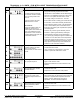
THE SECOND AND THIRD PROCEDURES ARE PERFORMED WITH THE BLOWER RUNNING
.
Second Procedure is an operational test to determine if the switch contacts are open or closed while the
blower is running and pressure is applied to the switch. The wires to the switch remain disconnected
and a
continuity test is performed as in the first procedure above. Ensure the wires ends do not touch/short to ground.
Ensure the sensing tube is properly connected at both ends and test for continuity with the blower running at full
speed. Note the condition of the switch contacts; whether open or closed.
Normally open air pressure switches must close during operation and normally closed air pressure switches must
remain closed throughout the heating cycle on A. O. Smith fan assisted water heaters. This information can
usually be found in the sequence of operation section of the owner’s manual and/or service manual for the
product. Contact the A. O. Smith technical information center (800 527-1953) for more information.
Normally open switches:
If the air pressure switch being tested is a normally open switch, it must close it’s
contacts (activate) before ignition can occur. If the continuity test indicates a normally open switch’s contacts
have closed while the blower is running, the switch is operating correctly. If the continuity test indicates the
switch contacts are remaining open while the blower is running the third “pressure test” procedure will have to be
performed. This will determine if the switch is defective or if the switch contacts are failing to close because the
pressure being sensed has not reached the “activation point” for the switch. This is covered on the next page.
Normally closed switches:
If the air pressure switch being tested is a normally closed switch, the switch
contacts must remain closed throughout the heating cycle. If the continuity test indicates a normally closed
switch’s contacts remain closed while the blower is running, the switch is operating correctly. If the continuity test
indicates the switch contacts are opening after the blower starts the third “pressure test” procedure will have to
be performed. This will determine if the switch is defective or if the switch contacts are opening because the
pressure being sensed has reached or exceeded the “activation point.” This will be covered on the next page.
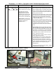
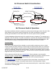
Air Pressure Switch Testing
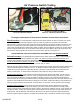
Continuity Test With Ohm Meter
Power-Vent Residential Model
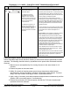
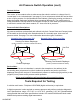
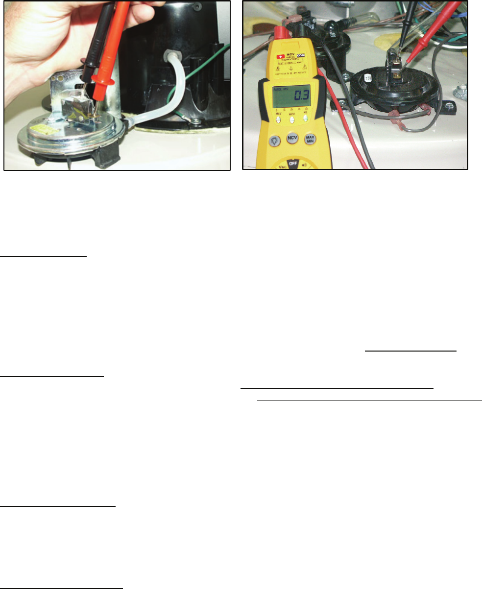
Continuity Test With Ohm Meter
BTH 120 - 250 Blocked Exhaust Switch
AHSA02307 4 of 8