
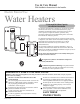
Use & Care Manual

CAUTION: The presence of
water in the piping and water
heater does not provide
sufficient conduction for a
ground. Non-metallic piping,
dielectric unions, flexible
connectors etc. can cause the
water heater to be electrically
isolated.
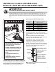
Electrical Connections
All wiring must conform to local codes or
latest edition of National Electrical Code
ANSI/NFPA 70.
The voltage requirements and wattage load
for the water heater are specified on the
rating plate on the front of the water heater.
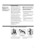
2
1
/2 gallon models are supplied with a plug
connected power supply cord for use only
in 120 VAC applications. The cord must
be connected to a properly grounded
receptacle on a branch circuit with copper
conductors, an over current protection
device and a suitable disconnect means. If
desired, straight field wiring connections
can be made to these models by removing
the access cover on front of heater and
disconnecting the cord set from the
thermostat and the grounding plug. Remove
the cord set and strain relief bushing from
the junction bracket. The hole in the
junction bracket will accommodate 1/2″ or
3/4″ electrical fittings. Refer to wiring
diagrams in the back of this manual for
wiring connections.
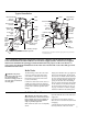
6 through 30 gallon models are completely
wired to the junction bracket inside jacket
at front of water heater. An opening for
1/2″ or 3/4″ electrical fitting is provided
for field wiring connections. A separate
branch circuit with copper conductors,
overcurrent protective device and suitable
disconnecting means must be provided by
a qualified electrician. Refer to wiring
diagrams in the back of this manual for
wiring connections.
The branch circuit wiring should include
either:
Metallic conduit or metallic sheathed
cable approved for use as a grounding
conductor and installed with fittings
approved for the purpose.
Non-metallic sheathed cable, metallic
conduit or metallic sheathed cable
not approved for use as a ground
conductor shall include a separate
conductor for grounding. It should be
attached to the ground terminals of
the water heater and the electrical
distribution box.
8
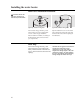
Installing the water heater.
NOTICE: This guide
recommends minimum
branch circuit sizing and
wire size based on National
Electric Code. Refer to
wiring diagrams in this
manual for field wiring
connections.
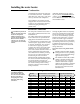
Branch Circuit Sizing and Wire Size Guide
Total Water Recommended Over Current Protection Copper Wire Size AWG Based
Heater Wattage (fuse or circuit breaker amperage rating) on N.E.C. Table 310-16 (75°C.)
120V 208V 240V 120V 208V 240V
1500* 20 15 15 12 14 14
1700 20 15 15 12 14 14
2000 25 15 15 10 14 14
2500 30 15 15 10 14 14
3000 35 20 20 8 12 12
3500 – 25 20 – 10 12
3800 – 25 20 – 10 12
4000 – 25 25 – 10 10
4500 – 30 25 – 10 10
5000 – 30 30 – 10 10
5500 – 35 30 – 8 10
6000 – 40 35 – 8 8
9000 – – 50 – – 8
*Less than 1500 watts may be wired 14 gauge with 15 amp protection. Check Local Electrical Codes, as they will also apply.
Condensation
Condensation can form on the tank when
it is first filled with water. Condensation
might also occur with a heavy water draw
and very cold inlet water temperature.
This condition is not unusual, and will
disappear after the water becomes heated.
If, however, the condensation continues,
examine the piping and fittings for
possible leaks.
Additional information on this subject
may be found at www
.rheem.com under
“Library”. Scroll down to the Technical
Service Bulletins 1300 Series Section and
choose Bulletin #1303.