INSTALLATION INSTRUCTIONS 13 & 14.5 SEER SERIES CONDENSING UNITS 11⁄2 - 5 TONS FEATURING INDUSTRY STANDARD R-410A REFRIGERANT R-410 NOTE: Appearance of unit may vary. ! RECOGNIZE THIS SYMBOL AS AN INDICATION OF IMPORTANT SAFETY INFORMATION! ! WARNING THESE INSTRUCTIONS ARE INTENDED AS AN AID TO QUALIFIED, LICENSED SERVICE PERSONNEL FOR PROPER INSTALLATION, ADJUSTMENT AND OPERATION OF THIS UNIT. READ THESE INSTRUCTIONS THOROUGHLY BEFORE ATTEMPTING INSTALLATION OR OPERATION.
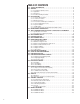
TABLE OF CONTENTS 1.0 SAFETY INFORMATION . . . . . . . . . . . . . . . . . . . . . . . . . . . . . . . . . . . . . . . . . . . . 3 2.0 GENERAL . . . . . . . . . . . . . . . . . . . . . . . . . . . . . . . . . . . . . . . . . . . . . . . . . . . . . . . 4 2.1 Checking Product Received. . . . . . . . . . . . . . . . . . . . . . . . . . . . . . . . . . . . . . 4 2.2 Application . . . . . . . . . . . . . . . . . . . . . . . . . . . . . . . . . . . . . . . . . . . . . . . . . . . 4 2.3 Dimensions . . . . . . . .
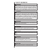
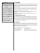
1.0 SAFETY INFORMATION ! WARNING THESE INSTRUCTIONS ARE INTENDED AS AN AID TO QUALIFIED LICENSED SERVICE PERSONNEL FOR PROPER INSTALLATION, ADJUSTMENT AND OPERATION OF THIS UNIT. READ THESE INSTRUCTIONS THOROUGHLY BEFORE ATTEMPTING INSTALLATION OR OPERATION. FAILURE TO FOLLOW THESE INSTRUCTIONS MAY RESULT IN IMPROPER INSTALLATION, ADJUSTMENT, SERVICE OR MAINTENANCE POSSIBLY RESULTING IN FIRE, ELECTRICAL SHOCK, PROPERTY DAMAGE, PERSONAL INJURY OR DEATH.
! WARNING THE MANUFACTURER’S WARRANTY DOES NOT COVER ANY DAMAGE OR DEFECT TO THE AIR CONDITIONER CAUSED BY THE ATTACHMENT OR USE OF ANY COMPONENTS. ACCESSORIES OR DEVICES (OTHER THAN THOSE AUTHORIZED BY THE MANUFACTURER) INTO, ONTO OR IN CONJUNCTION WITH THE AIR CONDITIONER. YOU SHOULD BE AWARE THAT THE USE OF UNAUTHORIZED COMPONENTS, ACCESSORIES OR DEVICES MAY ADVERSELY AFFECT THE OPERATION OF THE AIR CONDITIONER AND MAY ALSO ENDANGER LIFE AND PROPERTY.
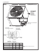
2.3 (SEE FIGURE 1) AIR DISCHARGE: ALLOW 60” MINIMUM CLEARANCE. w FIGURE 1 DIMENSIONS A-00008 AIR INLETS L (LOUVERED PANELS) ALLOW 6” MINIMUM CLEARANCE SERVICE ACCESS ALLOW 24” CLEARANCE H NOTE: GRILLE APPEARANCE MAY VARY. SEE DETAIL A DIMENSIONAL DATA 13 Seer Model Size 18, 24 30, 36, 42 14.5 Seer Model Size 48 60 18, 24, 30 36, 42, 48, 49,56, 60 Height “H” (in.) [mm] 241⁄4 [616] 241⁄4 [616] 273⁄8 [702] 353/8 [913] Length “L” (in.
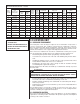
2.4 ELECTRICAL & PHYSICAL DATA (SEE TABLE 1) TABLE 1 ELECTRICAL AND PHYSICAL DATA – 13 SEER Electrical Model Number 13 SEER 1-PHASE Physical Compressor Phase Frequency (Hz) Voltage (Volts) Rated Load Amperes (RLA) Locked Rotor Amperes (LRA) Fuse or HACR Circuit Breaker Outdoor Coil Fan Motor Minimum Full Load Circuit Amperes Ampacity No. (FLA) Amperes Minimum Maximum Face Area2 Rows Amperes Amperes Sq. Ft. [m ] CFM [L/s] Refrig. Per Circuit Oz. [g] Weight Net Lbs. [kg] Shipping Lbs. [kg] Rev.
TABLE 1 - continued ELECTRICAL AND PHYSICAL DATA – 14.5 SEER Electrical Physical Compressor Model Number 14.5 SEER Phase Frequency (Hz) Voltage (Volts) Rated Load Amperes (RLA) Locked Rotor Amperes (LRA) Fuse or HACR Circuit Breaker Outdoor Coil Fan Motor Minimum Full Load Circuit Amperes Ampacity No. (FLA) Amperes Minimum Maximum Face Area2 Rows Amperes Amperes Sq. Ft. [m ] CFM [L/s] Refrig. Per Circuit Oz. [g] Weight Net Lbs. [kg] Shipping Lbs. [kg] Rev. 3/11/2010 18 1-60-208/230 9/9 48 0.
NOTE: These units must be installed outdoors. No ductwork can be attached, or other modifications made, to the discharge grille. Modifications will affect performance or operation. 3.3 OPERATIONAL ISSUES • • • IMPORTANT: Locate the condenser in a manner that will not prevent, impair or compromise the performance of other equipment horizontally installed in proximity to the unit. Maintain all required minimum distances to gas and electric meters, dryer vents, exhaust and inlet openings.
4.0 REFRIGERANT CONNECTIONS All units are factory charged with Refrigerant 410A. All models are supplied with service valves. Keep tube ends sealed until connection is to be made to prevent system contamination. 5.0 TOOLS REQUIRED FOR INSTALLING & 5.0 SERVICING R-410A MODELS Manifold Sets: -Up to 800 PSIG High Side -Up to 250 PSIG Low Side -550 PSIG Low Side Retard Manifold Hoses: -Service Pressure Ratiing of 800 PSIG Recovery Cylinders: -400 PSIG Pressure Rating -Dept.
6.0 REPLACEMENT UNITS To prevent failure of a new condensing unit, the existing evaporator tubing system must be correctly sized and cleaned or replaced. Care must be exercised that the expansion device is not plugged. For new and replacement units, liquid line filter drier sould be installed and refrigerant tubing should be properly sized. Test the oil for acid. If positive, a suction line filter drier is mandatory.
the unit and 15 feet of standard size interconnecting liquid and vapor lines. For different lengths, adjust the charge as indicated below. 1/4” ± 0.2 oz. per foot 5/16” ± 0.3 oz. per foot 3/8” ± 0.5 oz. per foot 1/2” ± 1.0 oz. per foot 9.2 MAXIMUM LENGTH OF LINES The maximum length of interconnecting line is 150 feet. Always use the shortest length possible with a minimum number of bends. Additional compressor oil is not required for any length up to 150 feet.
• • If tubing is to be run underground, it must be run in a sealed watertight chase. Use care in routing tubing and do not kink or twist. Use a tubing bender on the vapor line to prevent kinking. The vapor line must be insulated to prevent dripping (sweating) and prevent performance losses. Armaflex and Rubatex are satisfactory insulations for this purpose. Use 1/2” minimum insulation thickness, additional insulation may be required for long runs. Check Table 2 for the correct vapor line size.
TABLE 3 LIQUID LINE SIZE – OUTDOOR UNIT ABOVE INDOOR COIL System Capacity Line Size Line Size Connection Size (Inch O.D.) (Inch I.D.) [mm] [mm] Liquid Line Size Outdoor Unit Above Indoor Coil (Cooling Only - Does not apply to Heat Pumps) 25 [7.8] Total Equivalent Length - Feet [m] 50 [15.2] 75 [22.9] 100 [30.5] 125 [38.1] 150 [45.7] Minimum Vertical Separation - Feet [m] 11⁄2 Ton 3/8” [9.5] 2 Ton 3/8” [9.5] 21⁄2 Ton 3/8” [9.5] 3 Ton 3/8” [9.5] 31⁄2 Ton 3/8” [9.5] 4 Ton 3/8” [9.
10.0 EVACUATION PROCEDURE Evacuation is the most important part of the entire service procedure. The life and efficiency of the equipment is dependent upon the thoroughness exercised by the serviceman when evacuating air and moisture from the line set and indoor coil. Air in the system causes high condensing temperatures and pressure, resulting in increased power input and non-verifiable performance.
13.0 CHECKING REFRIGERANT CHARGE Charge for all systems should be checked against the Charging Chart inside the access panel cover. Before using the chart, the indoor conditions must be within 2°F of desired comfort conditions and system must be run until operating conditions stabilize (15 min. to 30 min.) ! CAUTION THE TOP OF THE SCROLL COMPRESSOR SHELL IS HOT. TOUCHING THE COMPRESSOR TOP MAY RESULT IN SERIOUS PERSONAL INJURY. IMPORTANT: Do not operate the compressor without charge in system.
13.3 FINAL LEAK TESTING After the unit has been properly evacuated and charged, a halogen leak detector should be used to detect leaks in the system. All piping within the condensing unit, evaporator, and interconnecting tubing should be checked for leaks. If a leak is detected, the refrigerant should be recovered before repairing the leak. The Clean Air Act prohibits releasing refrigerant into the atmosphere. ! WARNING 14.
15.0 FIELD INSTALLED ACCESSORIES 15.1 COMPRESSOR CRANKCASE HEAT (CCH) While scroll compressors usually do not require crankcase heaters, there are instances when a heater should be added. Refrigerant migration during the off cycle can result in a noisy start up. Add a crankcase heater to minimize refrigerate migration, and to help eliminate any start up noise or bearing “wash out.” NOTE: The installation of a crankcase heater is recommended if the system charge exceeds the values listed in Table 6.
FIGURE 2 *IF MAXIMUM OUTLET TEMPERATURE RISE IS DESIRED, IT IS RECOMMENDED THAT CONTROL WIRING FOR GAS OR OIL FURNACE W1 (W/BK) AND W2 (W/BL) BE JUMPERED TOGETHER.
17.0 TROUBLE SHOOTING In diagnosing common faults in the air conditioning system, it is useful to present the logical pattern of thought that is used by experienced technicians. The charts which follow are not intended to be an answer to all problems, but only to guide your thinking as you attempt to decide on your course of action. Through a series of yes and no answers, you will follow the logical path to a likely conclusion. Use these charts as you would a road map, if you are a beginning technician.
17.
17.3 SUPERHEAT CALCULATION TABLE 7 TEMPERATURE PRESSURE CHART TEMP (Deg. F) R-410A PSIG -150 -140 -130 -120 -110 -100 -90 -80 -70 -60 -50 -40 -35 -30 -25 -20 -15 -10 -5 0 5 10 15 20 25 30 35 40 45 50 55 60 65 70 75 80 85 90 95 100 105 110 115 120 125 130 135 140 145 150 — — — — — — — — — 0.4 5.1 10.9 14.2 17.9 22.0 26.4 31.3 36.5 42.2 48.4 55.1 62.4 70.2 78.5 87.5 97.2 107.5 118.5 130.2 142.7 156.0 170.1 185.1 201.0 217.8 235.6 254.5 274.3 295.3 317.4 340.6 365.1 390.9 418.0 446.5 476.5 508.0 541.
17.5 GENERAL TROUBLE SHOOTING CHART ! WARNING DISCONNECT ALL POWER TO UNIT BEFORE SERVICING. CONTACTOR MAY BREAK ONLY ONE SIDE. FAILURE TO SHUT OFF POWER CAN CAUSE ELECTRICAL SHOCK RESULTING IN PERSONAL INJURY OR DEATH.
18.0 WIRING DIAGRAMS FIGURE 3 18.
FIGURE 4 18.
FIGURE 5 18.3 PSC OD FAN MOTOR THREE-PHASE WIRING DIAGRAM WIRING DIAGRAM WIRING SCHEMATIC AUX G/Y GND. CCH OPT. OPT.
CM 0111