
Use and Care Manual

13
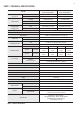
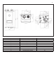
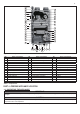
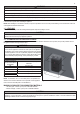
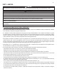
NO Name of Component NO Name of Component NO Name of Component
1 Pressure Relief Valve 15 3-Way Valve 29 Heating Return Thermistor
2 Exhaust 16 DHW Plate Heat Exchanger 30 Water Flow Sensor
3 Air Vent 17 DHW Thermistor 31 Flow Control Valve
4 Igniter 18 DHW Connection 32 Air Pressure Switch
5 Exhaust Thermistor 19 Heating Supply Connection 33 Pressure Sensor
6 Ignition Rod 20 Water Leakage Detector 34 Secondary Heat Exchanger
7 Burner Limit Switch 21 AC 24V Transformer 35 Gas Valve
8 High Limit Switch 22 Auto Feeder Connection 36 Flame Sensor
9 Heating Supply Thermistor 23 Condensate Trap 37 Burner
10 Primary Heat Exchanger 24 Heating Return Connection (Filter) 38 AGM (Air Gas Mixer)
11 Heating Outlet Pipe 25 DHW Cold Water Connection 39 Fan Motor
12 Manual Power Switch 26 Gas Connection 40 Air Inlet Filter
13 Control Panel 27 Circulation Pump 41 Air Intake
14 Circuit Board 28 DHW Cold Water Thermistor
Figure 2 – Model Components
Table 6 – Component List
IMPORTANT
CAUTION
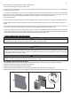
▪ A. UNCRATING THE APPLIANCE
UNCRATING APPLIANCE – Any claims for damage or shortage in shipment must be led immediately against the transportation company by the
consignee.
Cold weather handling – If appliance has been stored in a very cold location (below 0°F) before installation, handle with care until the plastic
components come to room temperature.
PART 4 –PREPARE APPLIANCE LOCATION
Remove all sides of the shipping crate to allow the appliance to be lifted into its installation location.
2. Page 13
1
4
7
8
11
12
14
15
16
18
19
20
21
22
23
24
25
26
27
28
29
30
31
32
34
33
35
36
37
38
2
39
40
41
3
5
6
17
9
10
13