
Use and Care Manual

21
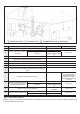
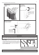
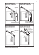
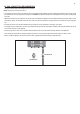
Figure 6 – Vent Termination Detail
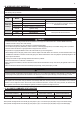
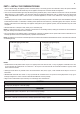
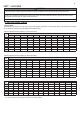
Table 9 – Vent Termination Clearances
NOTE: For clearances not specied in ANSI Z223.1/NFPA 54 or CAN/CSA-B 149.1, please use clearances in accordance with local installation codes
and the requirements of the gas supplier.
DESCRIPTION US CANADA
A
Clearance above grade, veranda, porch, deck, or balcony 1 foot (30 cm)
B
Clearance to window or door that may
be opened
Direct Vent 1 foot
36 in (91 cm)
Power Vent
4 feet below or to side of
opening; 1 foot above open-
ing
C
Clearance to permanently closed window *
D
Vertical clearance to ventilated soft located above the terminal within a hori-
zontal distance of 2 feet from the center line of the terminal
*
E
Clearance to unventilated soft *
F
Clearance to outside corner *
G
Clearance to inside corner *
H
Clearance to each side of center line extended above meter / regulator as-
sembly
*
I
Clearance to service regulator vent outlet *
Above a regulator within 3
feet (91 cm) horizontally of
the vertical center line of
the regulator vent outlet to a
maximum vertical distance of
15 ft (4.5 m)
J
Clearance to non-mechanical air sup-
ply inlet to building or the combustion
air inlet to any other appliance
Direct Vent 1 foot
3 feet (91 cm)
Power Vent
4 feet below or to side of
opening; 1 foot above open-
ing
K
Clearance to a mechanical air supply inlet
3 feet above if within 10 feet
horizontally
6 feet (1.83 cm)
L
Clearance above paved sidewalk or
driveway located on public property
Direct Vent *
7 feet (2.13 m)
Power Vent 7 feet
M
Clearance under veranda, porch, deck, or balcony * 1 foot (30 cm)