
Use and Care Manual

25
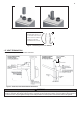
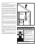
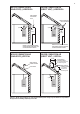
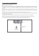
Figure 10 – Direct Vent, Vent Terminations (with Optional Kits)
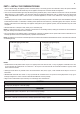
Figure 11 – Screen Installation
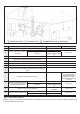
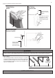
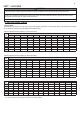
Figure 8 – Transitioning from 3" to 2" Vent Pipe
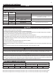
WARNING
All PVC vent pipes must be glued, properly supported, and the exhaust must be pitched a minimum of ¼" per foot back to the appliance to allow
drainage of condensate. When placing support brackets on vent piping, the rst bracket must be within 1 foot of the appliance and the balance at
4 foot intervals on the vent pipe. Appliance venting must be readily accessible for visual inspection for the rst three feet from the appliance.
2. Direct Vent, Optional Horizontal and Vertical Vent Kits
3. Screen Installation
After connecting the intake air and exhaust vent pipes, it is required
to install the included screens into the exhaust vent and intake pipe
terminations to prevent damages to the unit due to blockages. Clean
the vent terminations and glue the screens into the terminations. See
Figure 13 for installation detail.
3”(7.6cm) Vent Screen
1/4”(0.6cm) Mesh
Two screens of 2 “and 3” are provided. Please purchase and install additional screens if
necessary.
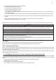
SAFETY INSTRUCTIONS
Do not connect any other appliance vents to the appliance exhaust vent or intake pipes.
Exhaust
Air Inlet
Min. 12 ”
above grade
or snow level
Exhaust
Air-inlet around
Perimeter
Sidewall Venting with Kit
G
EXHAUST
INTAKE
Sidewall Venting
with Concentric Vent
Kit
MAINTAIN 12 ” MINIMUM
CLEARANCE ABOVE
HIGHEST ANTICIPATED
SNOW LEVEL OR GRADE,
CONCENTRIC VENT KIT
1” MIN.
IMPORTANT:
INTAKE LEG MUST
BE FACING UP
EXHAUST
INTAKE
Roof Venting
w
ith Concentric Vent
K
it
12”OVER MAXIMUM SNOW
LEVEL OR 24
” - WHICHEVER
IS GREATER
CO
NCENTRIC VENT KIT
NOTE: EXTEND VENT RUNS WHEN
TRANSITIONING TO A LARGER
DIAMETER MUST ALWAYS TAKE
PLACE IN A VERTICAL POSITION
Sidewall Venting with
Concentric Vent Kit
Roof Venting
Concentric Vent
Kit
Sidewall Venting
with Kit