
Use and Care Manual

30
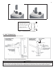
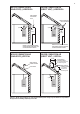
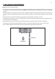
Figure 15 – Gas Line with Shut-Off Valve Detail
1. The gas connection tting on the appliance is 3/4" male NPT.
NOTE: The pipe size must not be less than ½".
2. The supply line must be sized for the maximum output of the appliance being installed. If there are additional gas appliances from the main supply
line, measure the size of the supply line according to the COMBINED total maximum BTUH draw for the appliances as if they were operating at the
same time.
3. Measure the length of the gas supply line from the gas meter to the appliance. Appliance must be installed downstream of the gas meter to ensure
adequate gas supply. Use the tables in this manual or refer to the gas line manufacturer’s sizing information to determine the correct supply pipe
size.
4. A manual gas shut-off valve should be installed in the gas supply line close to the appliance. See Figure 15 for detail.
5. To facilitate any future maintenance, it is also recommended that an approved gas union tting be installed in the supply line between the shut-off
valve and the connection on the appliance.
6. Test the gas pressure to make sure it meets the minimum standards and does not exceed the maximum standards of the appliance.
7. Leak test the gas line pipe before placing the appliance in operation. Only use approved leak detector liquid solutions to check for leaks.
8. Do not operate the appliance until all connections have been completed and the heat exchanger is lled with water.
▪ B. GAS CONNECTION REQUIREMENTS
GAS VALVE OFF
GAS VALVE ON