Installation and Start-Up Manual GEN12S, GEN15S, GEN20B & GEN25B 12000 / 15000 Watt Residential Generator System Questions? Help is just a moment away! Call: Home Generator Helpline (877) 369-9400 M-F 8-5 CT Manual No. 202113GS Rev.
Thank you for purchasing this quality-built Rheem / Ruud home standby generator. We are pleased that you’ve placed your confidence in the Rheem or Ruud brand. When operated and maintained according to the instructions in this manual, your Rheem / Ruud generator will provide many years of dependable service. This manual contains safety information to make you aware of the hazards and risks associated with installing residential standby generators and how to avoid them.
Table of Contents Important Safety Rules . . . . . . . . . . . . . . . . . . . . . . . . . . . . . . . . . . . . . 2 Installation . . . . . . . . . . . . . . . . . . . . . . . . . . . . . . . . . . . . . . . . . . . . . 5 Equipment Description. . . . . . . . . . . . . . . . . . . . . . . . . . . . . . . . . . . . . . . . . 5 Customer Responsibilities . . . . . . . . . . . . . . . . . . . . . . . . . . . . . . . . . . . . . . 5 Installer Responsibilities . . . . . . . . . . . . . . . . . . . . . . . . . . .
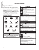
Save These Instructions Important Safety Rules WARNING The safety alert symbol ( ) is used with a signal word (DANGER, CAUTION, WARNING), a pictorial and/or a safety message to alert you to hazards. DANGER indicates a hazard which, if not avoided, will result in death or serious injury. WARNING indicates a hazard which, if not avoided, could result in death or serious injury. CAUTION indicates a hazard which, if not avoided, might result in minor or moderate injury.
WARNING Generator produces hazardous voltage. Failure to properly ground generator can result in electrocution. Failure to isolate generator from power utility can result in death or injury to electric utility workers due to backfeed of electrical energy. • When using generator for backup power, notify utility company. • Do not touch bare wires or receptacles. • Do not use generator with electrical cords which are worn, frayed, bare or otherwise damaged.
WARNING Starter and other rotating parts can entangle hands, hair, clothing, or accessories. • NEVER operate generator without protective housing or covers. • DO NOT wear loose clothing, jewelry or anything that may be caught in the starter or other rotating parts. • Tie up long hair and remove jewelry. CAUTION Installing the 15A fuse could cause the engine to start. • Observe that the 15 Amp fuse has been removed from the control panel for shipping.
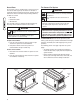
Installation Unpacking Precautions Equipment Description The unit is shipped bolted to its mounting pad, ready for installation. Avoid damage from dropping, bumping, collision, etc. Store and unpack carton with the proper side up, as noted on the shipping carton.
Generator Location WARNING Exhaust heat/gases can ignite combustibles or structures causing a fire. • DO NOT install the generator closer than 5 feet (1.5m) from any combustibles or structures with combustible walls having a fire resistance rating of less than 1 hour. • Keep at least 3 ft. (91 cm) clearance on all sides of generator including overhead. Before installing generator, consult with homeowner and convey the following guidelines which may affect the desired location.
Recommended Conduit Attachment Area Fuel Piping Connector 3/4” NPT Figure 2 — Generator Fuel and Conduit Attachment Locations, Oil Fill Side of Unit Lifting the Generator The generator weighs more than 560 pounds. Proper tools, equipment and qualified personnel should be used in all phases of handling and moving the generator. Two 48” lengths of 1” pipe (supplied by the installer) are required to lift the generator manually.
Access Doors The Gaseous Fuel System The generator system is equipped with an enclosure that has three access doors (Figure 4). The doors are named for a significant component located behind them. Starting with the side that has the fuel connection and proceeding clockwise, the doors are named: • Oil Fill door • Control Panel door • Oil Drain door Each generator system is equipped with two identical keys. These keys fit the locks that secure the access doors.
• Install the flexible, gaseous hose (supplied) between the generator system Fuel Inlet port and rigid piping to prevent thermal expansion or contraction from causing excessive stress on the piping material. NOTE: Where local conditions include earthquake, tornado, unstable ground, or flood hazards, special consideration shall be given to increase strength and flexibility of piping supports and connections.
Fuel Consumption Fuel Pipe Sizing See Figure 7 for estimated fuel supply requirements at half and full load for both natural gas and LP vapor. Figures 8 and 9 provide the maximum capacity of pipe in cubic feet of gas per hour for gas pressures of 0.5 psi or less and a pressure drop of 0.3 in. water column. Specific gravity of gas is shown. Listed values compensate for a nominal amount of restriction from bends, fittings, etc.
Fuel Comparison Chart The fuel comparison chart shown below is provided for your reference. Physical Properties Propane Natural Gas Normal Atmospheric State Gas Gas Boiling Point (in °F): Initial End -44 -44 -259 -259 Heating Value: BTU per gallon (Net LHV*) BTU per Gallon (Gross**) Cubic Feet (Gas) 83,340 91,547 2,500 63,310 Density*** 36.39 57.75 Weight† 4.24 2.65 Octane Number: Research Motor 110+ 97 110+ 1,000 *LHV (Low Heat Value) is the more realistic rating.
System Connections Compare this illustration with your generator to familiarize yourself with the location of these important connections: 10 Pole Connector Fault Contacts Transfer Switch Communication Remote LED Output +12 Volt DC, .5 Amp Output 2 Pole Connector 240 Volt Utility Wiring for the 10 Pole Connector: • Fault Contacts — Use NO, COM and NC to hook up a siren, light, etc. to alert for a fault. Contacts reverse state upon a fault condition.
System AC Connections Grounding the Generator A single-phase, three-wire AC connection system is used in the generator system. The stator assembly consists of a pair of stationary windings with two leads brought out of each winding. The junction of leads 22 and 33 forms the neutral lead, as shown schematically and as wiring diagram in Figure 10. A complete schematic and wiring diagram can be found in the illustrated parts list manual. NOTE: Neutral is not bonded to ground at generator.
System Control Panel Figure 11 depicts the generator system control panel, located inside the generator housing. Below are brief descriptions of the controls used during installation. More information may be found in the Operator’s Manual.
WARNING Storage batteries give off explosive hydrogen gas during recharging. Slightest spark will ignite hydrogen and cause explosion. Battery electrolyte fluid contains acid and is extremely caustic. Contact with battery contents will cause severe chemical burns. A battery presents a risk of electrical shock and high short circuit current. • DO NOT dispose of battery in a fire. • Do not allow any open flame, spark, heat, or lit cigarette during and for several minutes after charging a battery.
For a 15kW Generator: 4. Remove cap from LP inlet on T-valve (Figure 13). Figure 13 — T - Valve 5. 6. 7. 8. Remove fuel line from NG inlet. Place cap from LP inlet onto NG inlet. From oil fill access area, pull fuel line out of top hole. Remove and reverse fuel hose bushing and plug in sheet metal bulkhead. (Plug in top hole, bushing in bottom hole.) 9. Insert fuel hose in bottom hole towards fuel regulator. IMPORTANT: Failure to route fuel line through bottom hole may cause the fuel line to kink.
Engine Adjustment There are regional variances in the composition of natural gas. Each generator system is adjusted at the factory for NG operation. If the generator output voltage or frequency measured during Initial Start-Up (paragraph #9, earlier) is outside the listed ranges, the combustibility of the gas supplied at the installation site may be substantially different. To adjust the engine for this difference, proceed as follows. 1. Open the oil drain and control panel access doors. 2.
Controls All generator system controls are fully described in the Operator’s Manual. Please refer there for full information. Operation The primary source of generator system operating instructions is the Operator’s Manual. Please refer to the Operator’s Manual for detailed information. The following is a brief overview. The generator’s control panel houses a logic control circuit board. This control board constantly monitors utility power source voltage.
Notes 19
Schematic and Wiring Diagram for Models GEN12S and GEN20B 20
Schematic and Wiring Diagram for Models GEN15S and GEN25B 21