
Manual
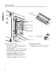
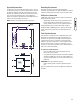
Table Of Contents
- TOC En
- Important Safety Rules
- Installation
- Equipment Description
- Customer Responsibilities
- Installer Responsibilities
- Unpacking Precautions
- Delivery Inspection
- Shipment Contents
- Required Specialty Tools/Equ...
- Generator Location
- Fuel and Electrical Inlet Di...
- Lifting the Generator
- Access Doors
- The Gaseous Fuel System
- Fuel Consumption
- Fuel Pipe Sizing
- Fuel Comparison Chart
- System Connections
- System AC Connections
- Grounding the Generator
- Utility Circuit Connection
- Fault Detection System
- System Control Panel
- Before Initial Start-up
- Fuel System Selection
- Initial Start-Up (No Load)
- Engine Adjustment
- Controls
- Operation
- TOC Sp
- Instrucciones Importantes de...
- Instalación
- Descripción del Equipo
- Responsabilidades del Cliente
- Responsabilidades del Instal...
- Precauciones al Momento del ...
- Inspección al Momento de la ...
- Contenido de la Caja
- Herramientas/Equipos Especia...
- Ubicación del Sistema de Gen...
- Dimensiones de la Entrada pa...
- Elevación del Generador
- Puertas de Acceso
- Sistema de Combustible Gaseoso
- Consumo de Combustible
- Dimensiones de la Cañería de...
- Cuadro de Comparación de Com...
- Conexiones de Sistema
- Conexión a Tierra del Generador
- Interconexiones del Circuito...
- Sistema de Detección de Fallas
- Panel de Control del Sistema
- Antes del Arranque Inicial d...
- Selección del Sistema de Com...
- Arranque Inicial (sin carga)
- Ajuste del Motor
- Operación
- Configuración del Temporizad...
- Inspección Posterior a la In...
- TOC Fr
- Directives de Sécurité Impor...
- Installation
- Description de l'Équipement
- Responsabilités de l'Acheteur
- Responsabilités de l'Install...
- Précautions Lors du Déballage
- Vérification de la Livraison
- Contenu de la Boîte
- Outils/Équipements Spécialis...
- Emplacement du Génératrice d...
- Dimensions pour l'Admission ...
- Soulèvement de la Génératrice
- Portes d'Accès
- Le Système de Combustible Ga...
- Consommation de Combustible
- Grosseur du Tuyau de Combust...
- Charte de Comparaison des Co...
- Connexions de Système
- Mise à la Masse de la Généra...
- Interconnexions du Circuit d...
- Système de Détection des Pannes
- Tableau de Commande du Système
- Avant le Démarrage Initial d...
- Sélection du Système de Comb...
- Demarrage Initial (sans charge)
- Réglage du Moteur
- Fonctionnement
- Réglage de la Minuterie de C...
- Vérification Installation
14
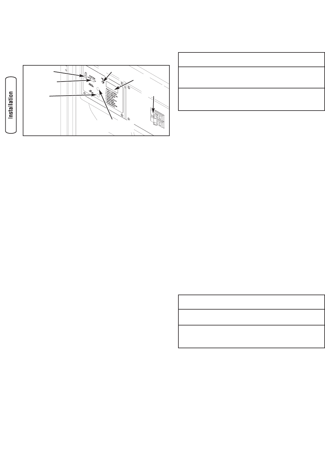
System Control Panel
Figure 11 depicts the generator system control panel, located
inside the generator housing. Below are brief descriptions of
the controls used during installation. More information may
be found in the Operator’s Manual.
System Switch
This two-position switch is the most important control on
the system and is used as follows:
•“AUTO” position is the normal operating position. If a
utility power outage is sensed, the system will start the
generator. When utility power is restored, lets the
engine stabilize internal temperatures, shuts off the
generator, and waits for the next utility power outage.
•“OFF” position turns off running generator, prevents
unit from starting and resets any detected faults.
15 Amp Fuse
Protects the generator system DC control circuits. If the fuse
has ‘blown’ (melted open) or was removed, the engine
cannot crank or start. Replace the fuse using only an
identical ATO 15A fuse. One spare fuse is supplied with the
unit.
Before Initial Start-up
Engine Oil
This engine is shipped from the factory filled with the
recommended oil. Before starting the engine, check oil level
and ensure that engine is serviced as described in the engine
operator’s manual.
Oil Considerations
Your generator system is equipped with an engine that has
been pre-run at the factory.
The system is filled with synthetic oil (API SJ/CF 5W-30W).
This allows for system operation in the widest range of
temperature and climate conditions.
NOTE: The use of synthetic oil does not alter the required oil
change intervals described in the engine operator’s manual.
Battery Connection
The generator system is supplied with a 12 Volt DC, AGM
type, 55 Amp-Hour, valve regulated battery. It is a sealed,
lead-acid rechargeable battery. It is installed in the unit and
the battery cables are connected at the factory. The unit’s
15 Amp fuse, which isolates the battery and prevents the unit
from starting, has been removed for shipping. The battery will
lose some charge charge prior to installation of the generator.
If battery voltage is below 12 Volts, charge the battery.
IMPORTANT: If battery voltage is below 5 Volts, it may not
take a charge and you will need a new battery.
Charging the Battery
If it is necessary to charge the battery, proceed as follows:
1. Set generator's system switch to OFF.
2. Remove 15 Amp fuse from control panel.
3. Disconnect negative battery cable to negative battery
terminal (indicated by NEGATIVE, NEG, or (-).
4. Charge battery with battery charger at 2 Amps until
battery holds 12 Volts.
NOTE: DO NOT exceed 13.7 Volts charging.
• DO NOT attempt to jump start the battery.
• Damage to equipment resulting from failure to follow this
instruction will void warranty.
NOTICE
Failure to disconnect negative battery cable will result in
equipment failure.
• Refer to engine manual for oil fill information.
• Damage to equipment resulting from failure to follow this
instruction will void warranty.
NOTICE
Any attempt to crank or start the engine before it has been
properly serviced with the recommended oil will result in
equipment failure.
Manual Over-Ride
Switch
Set Exercise
Switch
System Switch
Digital Display
15 Amp Fuse
Service Tool
Circuit
Breaker
Figure 11 — Generator System Control Panel