
Instructions / Assembly


2
Pump Installation
DO NOT install this pump outdoors. DO NOT
energize pump until properly installed and system is
checked for leak and completely filled.
Pumps are designed to circulate water from 40°F to
150°F. Pump is rated for working pressure of 125psi.
Electrical rating for pump is 115V, 1Ph, 60Hz.
!
Pump is suitable for indoor application only.
1. Turn remote control off, then disconnect electric power
to water heater.
2. Shut off the gas and incoming water valves to the
water heater.
3. Remove the front cover panel on the water heater.
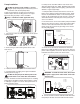
4. Install the pump according to the typical installation
drawing shown on page 3.
DO NOT install pump at the lowest point of the
system where it can collect dirt and sediment.
5. Lines should be cleaned and flushed prior to installing
pump. Water should be treated if total hardness of water
is 180 mg/L or higher so as not to affect performance of
pump and water heater.
6. Pump can be used with tankless water heater and
equivalent pipe length up to 400 ft. Equivalent pipe length
includes fittings, supply and return piping. (Based on 3/4”
diameter, L Type Copper Pipe).
7. Pump should be mounted such that the arrow at the
bottom of the pump is pointing towards the heater. Pump
must be mounted with the motor in a horizontal position.
Pump can be installed with the shaft vertical or where the
shaft falls below the horizontal plane if the system pres-
sure is over 20 PSI.
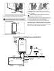
8. The wire harness for the recirculation pump is bundled
with the wire harness from the control board. Find a blue
connector with a black and white wire and remove the
female end of the connector by pressing on the release
tab and pulling lightly.
9. Locate the access hole at the bottom of the heater.
Remove the rubber grommet in the access hole. Run the
power cord through the access hole. Ensure strain relief is
locked into the bottom panel of the water heater.
WARNING: To avoid electrical shock, disconnect
the power supply to the water heater at the main
electrical unit.
10. Connect the blue connector with black and white wires
from pump to the blue connector inside the water heater.
!
Water Heater
Control
Board
Blue
connector (male)
BK
W
BK = Black
W = White
Label
Blue
connector (female)
Release Tab
Water Heater
Control
Board
PUMP
4 Amp
Fuse
Blue
connector
(male)
BK
W
Ground Wire
BK = Black
W = White
G = Green
BK
W
G
Ring Terminal
Label
Blue
connector
(female)
!
Access
hole. (Use
either one)
OK if over
20 psi
Standard
Allowable circulator mounting positions.
!